Camera specifications
| Sensor | CMOS |
| Pixel size | 7 µm × 7 µm |
| Line spacing | 7 µm between M-G & G-B & B-R |
| Spectral sensitivity | 400 nm – 960 nm |
| Resolution | 4096 × 4 lines |
| Full well capacity | 10 ke- and 40 ke- |
| Video output | 2 × CoaXPress 2.0 |
| Data format | 3 × 8/10/12 Bit color or 1 × 8/10/12 Bit mono or 4 × 8/10/12 RGB + Mono |
| Trigger Mode | Frame Start / Frame Active / Frame Burst Start / Line Start / External Encoder |
| Video output port | 2 × CXP-12 Micro-BNC |
| Digital I/O port | External I/O (15 pin HD D-Sub, male) |
| Power supply | PoC (Power over CoaXPress) or digital I/O port: 12 – 24V DC ± 10 %; 0.5 A @ 24 V |
| Debugging port | - |
| Lens mount / adapter | M42 × 1 mm / F-Mount, TFL |
| Housing dimensions | 62 mm × 62 mm × 62 mm |
| Weight | 0,35 kg |
| Temperature during operation | 0 °C – 60 °C; 32 °F – 140 °F |
| Humidity during operation | |
| Temperature during transport and storage | -20 °C – +85 °C; -4 °F – +185 °F |
| Protection category | IP50 |
| Certifications | CE, RoHS |
| General ambient conditions | |
| Transport | IEC 721-3-3:IE33 |
| Operation | IEC 721-3-3:IE21 |
| Storage | IEC 721-3-3:IE11 |
Line scan sensor
Sensor pixel arrangement
 Sensor line spacing and pixel arrangement of the 4k sensor
Spectral sensitivity
 Measured relative sensitivity of the color and the mono sensor
Sensor alignment and orientation
Mechanical dimensions
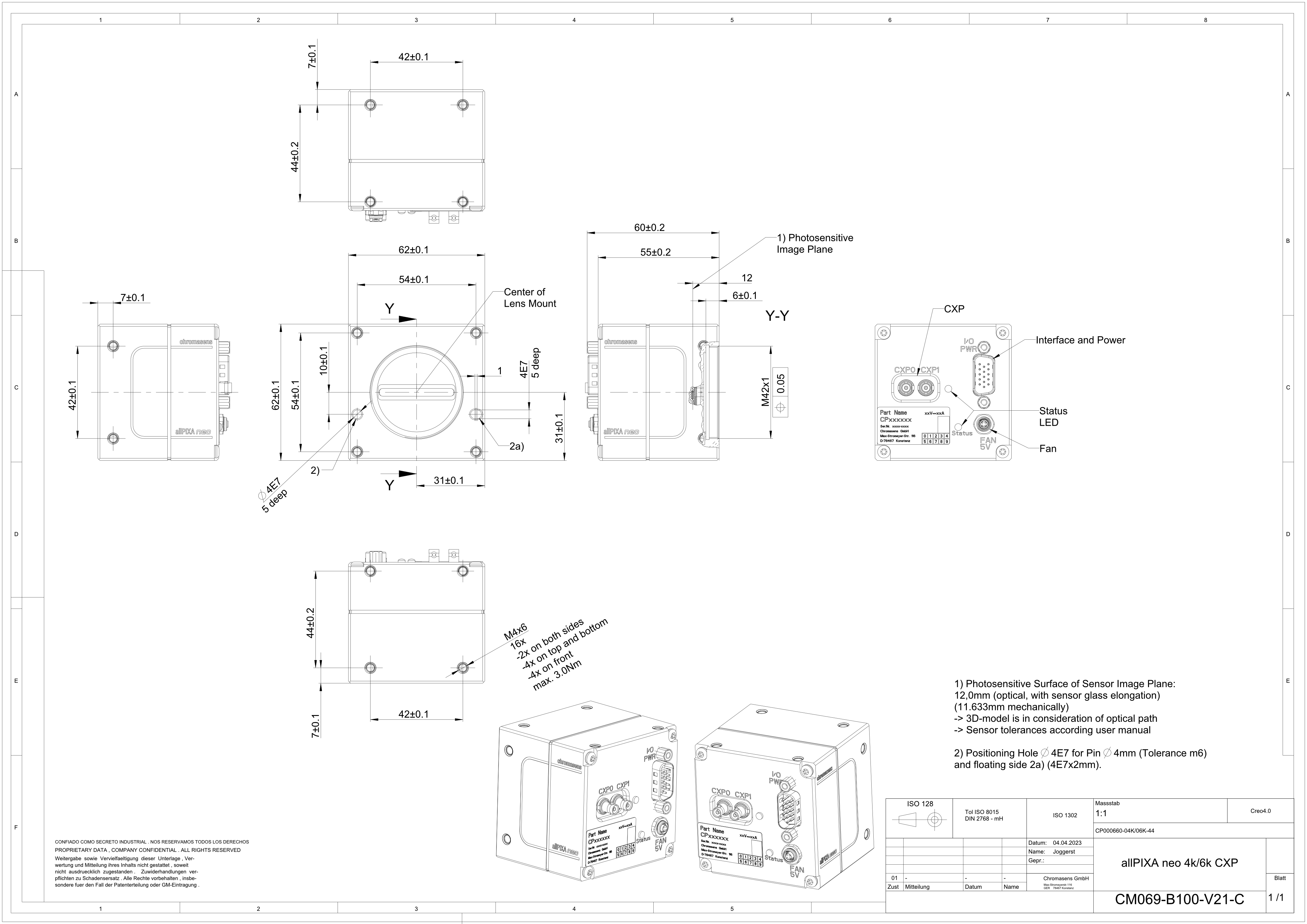 Dimensional drawing of the allPIXA neo 4k/6k CXP
Download as pdf-file
Interface specification
 | |||
| 1 | Video output port (2 × CoaXPress 2.0) and power supply | 2 | Digital I/O port and power supply |
| 3 | Connector for additional fan | 4 | Status LED |
Line rate
| Configuration (8 bit) | Line rate |
|---|---|
| Mono | 300 kHz |
| RGB | 105 kHz |
| RGB + Mono (NIR) | 80 kHz |
Power supply
You can either use Power over CoaXPress (PoC) or the power supply of the external digital I/O port.
Digital I/O port
The following connector is required for the digital I/O port:
- 15 pin HD D-Sub (female)
 Pin allocation D-Sub connector (male) of the camera
You can configure the digital I/O port as RS422 or as single-ended input or output. It is also possible to configure one output as RS422 and the other output as single-ended.
RS422 configuration
| Pin | Line definition for RS422 configuration | Signal RS422 | Configuration proposal |
|---|---|---|---|
| 1 | Line 1 | In1+ | Encoder Source A, Line Start |
| 2 | In1– | Encoder Source A\, Line Start\ | |
| 3 | Line 2 | In2+ | Encoder Source B, Fame Start, Frame Active |
| 4 | In2– | Encoder Source B\, Fame Start\, Frame Active\ | |
| 5 | GND (Signals) | Signals Ground | |
| 6 | Line 3 | In3+/Out3+ | Encoder Source A, Fame Start, Frame Active, Line Start, User Output3+ |
| 7 | In3–/Out3– | Encoder Source A\, Fame Start\, Frame Active\, Line Start\, User Output3- | |
| 8 | Line 4 | In4+/Out4+ | Encoder Source A, Fame Start, Frame Active, Line Start, User Output4+, MS-In+ |
| 9 | In4–/Out4– | Encoder Source A\, Fame Start\, Frame Active\, Line Start\, User Output4-, MS-In- | |
| 10 | GND (PWR) | Camera Power Ground | |
| 11 | Line 5 | Out5+ | User Output5+, MS-Out+ |
| 12 | Out5– | User Output5-, MS-Out- | |
| 13 | Line 6 | Out6+ | User Output6+ |
| 14 | User Output6- | ||
| 15 | Vcc (PWR) | Camera Power DC +12 V – +24 V |
Single-Ended (SE) configuration
The input threshold voltage can be configured globally to 3.3 V, 5 V, 12 V and 24 V. The Maximum input voltage is 28 V. The set voltage level is then active for all single ended inputs and outputs.
| Pin | Line definition for Single-Ended configuration | Signal Single-Ended | Configuration proposal |
|---|---|---|---|
| 1 | Line 1 | In1 (3.3 V, 5 V, 12 V, 24 V) | Encoder Source A, Line Start |
| 2 | -- | -- | -- |
| 3 | Line 2 | In2 (3.3 V, 5 V, 12 V, 24 V) | Encoder Source B, Fame Start, Frame Active |
| 4 | -- | -- | -- |
| 5 | GND (Signals) | Signals Ground | |
| 6 | Line 3 | In3 (3.3 V, 5 V, 12 V, 24 V) Out3 (3.3 V) | Encoder Source A, Fame Start, Frame Active, Line Start, User Output3+ |
| 7 | -- | -- | -- |
| 8 | Line 4 | In4 (3.3 V, 5 V, 12 V,24 V) Out4 (3.3 V) | Encoder Source A, Fame Start, Frame Active, Line Start, User Output4+ |
| 9 | -- | -- | -- |
| 10 | GND (PWR) | Camera Power Ground | |
| 11 | Line 5 | In5 (3.3 V) Out5 (3.3 V) | LED Flash Out 3, User Output5 |
| 12 | Line 7 | In7 (3.3 V) Out7 (3.3 V) | LED Flash Out 2, User Output7 |
| 13 | Line 6 | In6 (3.3 V) Out6 (3.3 V) | LED Flash Out 0, User Output6 |
| 14 | Line 8 | In8 (3.3 V) Out8 (3.3 V) | LED Flash Out 1, User Output8 |
| 15 | Vcc (PWR) | Camera Power DC +12 V – +24 V |
LED status indicator
| Color code | Behaviour | Description |
|---|---|---|
 | Off | No power supply or the input voltage is out of range. |
 | Solid orange | The system is booting. |
 | Flash_1_1red | The device is powered but not connected (not applicable to a device reliant on PoCXP power). |
 | AlternateFlash_12_5 green/orange; shown for a minimum of 1s even if connection detection is faster | The Connection detection is in progress, PoCXP is active. |
 | Flash_12_5 orange; shown for a minimum of 1s even if connection detection is faster | The Connection detection is in progress, PoCXP is not in use. |
 | AlternateFlash_0_5 red/green | The device/host is incompatible, PoCXP is active. |
| AlternateFlash_0_5 red/orange | The device/host is incompatible, PoCXP is not in use. |
 | Solid red | PoCXP is over-current (host only). |
 | Solid green | The device/host is connected, but no data is transferred. |
 | Flash_1_ orange | The device/host is connected, waiting for event (e.g. trigger). |
 | Flash_12_5 green | The device/host is connected, data is being transferred. |
 | 500ms red pulse | Error during data transfer (e.g. CRC error, single-bit error) is detected. In case of multiple errors, there shall be at least two green Flash_12_5 pulses, before the next error is indicated. |
 | AlternateFlash_0_5 green/orange | A connection test packet is being sent. |
 | AlternateFlash_0_5 red/green/orange | The compliance test mode is enabled (device only). |
 | Flash_12_5 red | A system error (e.g. internal error) ocurred. |