Camera specifications
Sensor | CMOS |
Pixel size | 5 µm × 5 µm |
Line spacing | |
Spectral sensitivity | 400 nm – 960 nm |
Resolution | 6144 × 4 lines |
Full well capacity | 10 ke- and 40 ke- |
Video output | Single 10 GigE, GigE Vision® 2.0 compliant |
Data format | 3 × 8/10/12 Bit color or 1 × 8/10/12 Bit mono or 4 × 8/10/12 RGB + Mono |
Trigger Mode | Frame Start / Frame Active / Frame Burst Start / Line Start / External Encoder |
Video output port | RJ45 (10GBase-T) |
Digital I/O port | External I/O (15 pin HD D-Sub, male) |
Power supply | PoE (Power over Ethernet) or digital I/O port: 12 – 24V DC ± 10 %; 0.5 A @ 24 V |
Debugging port | - |
Lens mount / adapter | M42 × 1 mm / F-Mount, TFL |
Housing dimensions | 62 mm × 62 mm × 62 mm |
Weight | 0,35 kg |
Temperature during operation | 0 °C – 60 °C; 32 °F – 140 °F |
Humidity during operation | |
Temperature during transport and storage | -20 °C – +85 °C; -4 °F – +185 °F |
Protection category | IP50 |
Certifications | CE, RoHS |
General ambient conditions | |
Transport | IEC 721-3-3:IE33 |
Operation | IEC 721-3-3:IE21 |
Storage | IEC 721-3-3:IE11 |
Line scan sensor
Sensor pixel arrangement
 Left: Sensor line spacing and pixel arrangement of the 6k sensor
Right: Sensor line spacing and pixel arrangement of the 6k sensor with NIR
Spectral sensitivity
 Measured relative sensitivity of the color and the mono sensor
 Measured relative spectral sensitivity of the 6k sensor with NIR
Sensor alignment and orientation
![]() Alignment and orientation of the 6k sensor: Color + Mono
Alignment and orientation of the 6k sensor: Color + Mono
Mechanical dimensions
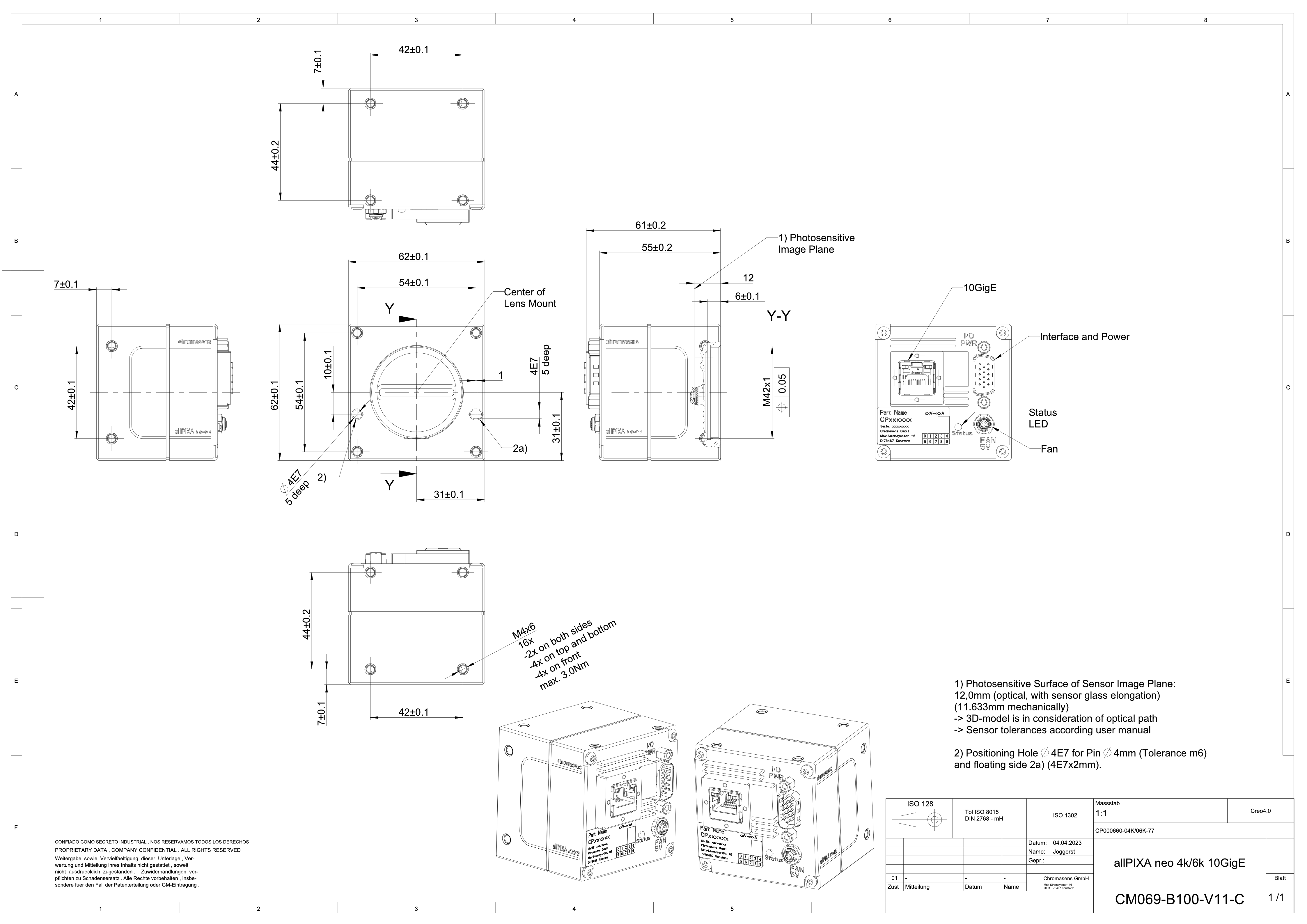 Dimensional drawing of the allPIXA neo 4k/6k 10GigE
Interface specification
.svg) | |||
| 1 | Video output port 10GigE (RJ45) and power supply | 2 | Digital I/O port and power supply |
| 3 | Status LED | 4 | Connector for additional fan |
Line rate
| Configuration (8 bit) | Line rate |
|---|---|
| Mono | 196.8 kHz |
| RGB | 65.3 kHz |
| RGB + Mono (NIR) | 50.0 kHz |
Power supply
You can either use Power over Ethernet (PoE) or the power supply of the external digital I/O port.
Digital I/O port
The following connector is required for the digital I/O port:
- 15 pin HD D-Sub (female)
 Pin allocation D-Sub connector (male) of the camera
You can configure the digital I/O port as RS422 or as single-ended input or output. It is also possible to configure one output as RS422 and the other output as single-ended.
RS422 configuration
| Pin | Line definition for RS422 configuration | Signal RS422 | Configuration proposal |
|---|---|---|---|
| 1 | Line 1 | In1+ | Encoder Source A, Line Start |
| 2 | In1– | Encoder Source A\, Line Start\ | |
| 3 | Line 2 | In2+ | Encoder Source B, Fame Start, Frame Active |
| 4 | In2– | Encoder Source B\, Fame Start\, Frame Active\ | |
| 5 | GND (Signals) | Signals Ground | |
| 6 | Line 3 | In3+/Out3+ | Encoder Source A, Fame Start, Frame Active, Line Start, User Output3+ |
| 7 | In3–/Out3– | Encoder Source A\, Fame Start\, Frame Active\, Line Start\, User Output3- | |
| 8 | Line 4 | In4+/Out4+ | Encoder Source A, Fame Start, Frame Active, Line Start, User Output4+, MS-In+ |
| 9 | In4–/Out4– | Encoder Source A\, Fame Start\, Frame Active\, Line Start\, User Output4-, MS-In- | |
| 10 | GND (PWR) | Camera Power Ground | |
| 11 | Line 5 | Out5+ | User Output5+, MS-Out+ |
| 12 | Out5– | User Output5-, MS-Out- | |
| 13 | Line 6 | Out6+ | User Output6+ |
| 14 | User Output6- | ||
| 15 | Vcc (PWR) | Camera Power DC +12 V – +24 V |
Single-Ended (SE) configuration
The input threshold voltage can be configured globally to 3.3 V, 5 V, 12 V and 24 V. The Maximum input voltage is 28 V. The set voltage level is then active for all single ended inputs and outputs.
| Pin | Line definition for Single-Ended configuration | Signal Single-Ended | Configuration proposal |
|---|---|---|---|
| 1 | Line 1 | In1 (3.3 V, 5 V, 12 V, 24 V) | Encoder Source A, Line Start |
| 2 | -- | -- | -- |
| 3 | Line 2 | In2 (3.3 V, 5 V, 12 V, 24 V) | Encoder Source B, Fame Start, Frame Active |
| 4 | -- | -- | -- |
| 5 | GND (Signals) | Signals Ground | |
| 6 | Line 3 | In3 (3.3 V, 5 V, 12 V, 24 V) Out3 (3.3 V) | Encoder Source A, Fame Start, Frame Active, Line Start, User Output3+ |
| 7 | -- | -- | -- |
| 8 | Line 4 | In4 (3.3 V, 5 V, 12 V,24 V) Out4 (3.3 V) | Encoder Source A, Fame Start, Frame Active, Line Start, User Output4+ |
| 9 | -- | -- | -- |
| 10 | GND (PWR) | Camera Power Ground | |
| 11 | Line 5 | In5 (3.3 V) Out5 (3.3 V) | LED Flash Out 3, User Output5 |
| 12 | Line 7 | In7 (3.3 V) Out7 (3.3 V) | LED Flash Out 2, User Output7 |
| 13 | Line 6 | In6 (3.3 V) Out6 (3.3 V) | LED Flash Out 0, User Output6 |
| 14 | Line 8 | In8 (3.3 V) Out8 (3.3 V) | LED Flash Out 1, User Output8 |
| 15 | Vcc (PWR) | Camera Power DC +12 V – +24 V |
LED Status indicator
| Color code | Behavior | Description |
|---|---|---|
 | Off | No power supply or the input voltage is out of range. |
 | Blue continuous | The device is OK and provides image data. Between image gaps the LED is off. |
 | Green continuous | The device is in power-up mode. |
 | Green blinking | The device is OK and ready. |
 | Yellow continuous | Warning-state: The device is operational. |
 | Red continuous | Error-state: The device is not operational. |