Calculation of PRNU
The following equation describes the calculation of the PRNU
CalibratedImage = (RawImage - DSNU) / PRNU
PRNU = (PRNUImage-DSNU)/TargetValue
CalibratedImage = Camera output with applied DSNU and PRNU
RawImage = Camera output image without any correction
TargetValue = Target Value of PRNU, default value is 255
PRNUImage = Acquired image of the white-reference
PRNU = Photo response non-uniformity
DSNU = Dark signal non-uniformity
Standard Method: PRNU reference generating (white diffuse surface)
Create a shading-reference with PRNU.
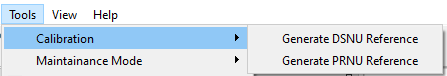
Acquire an image:
| |
|
|
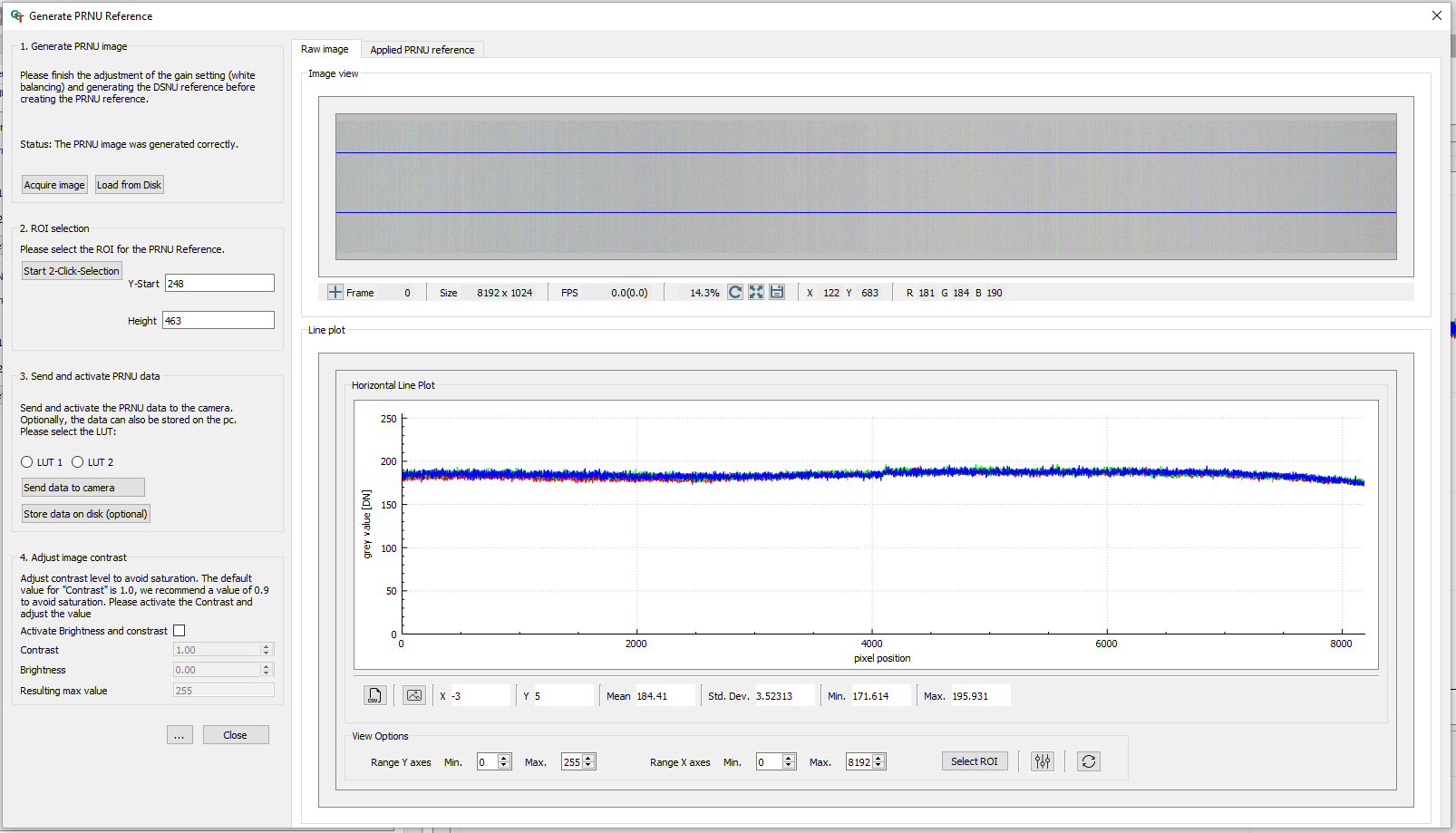
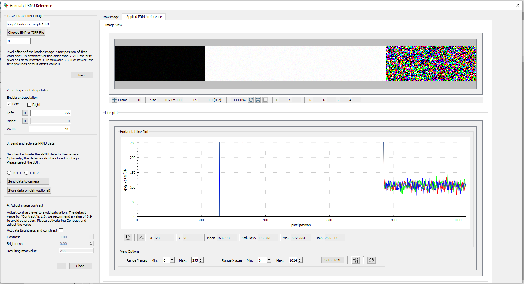
The Generate PRNU Reference wizard opens.
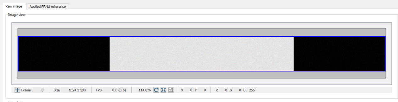
The raw image and the line plot of the image is displayed.
Send the calculated PRNU to the camera:
Activate brightness and contrast:
|
|
Independent Method: PRNU reference generating channel independent
Note
This function it available from the GCT version 3.2.
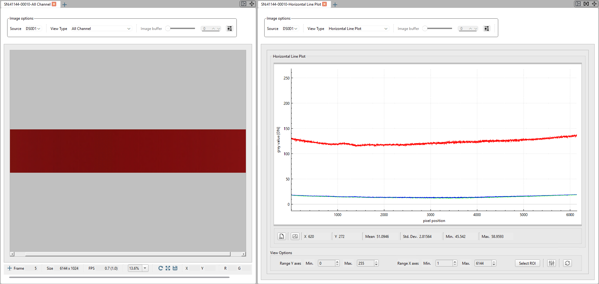
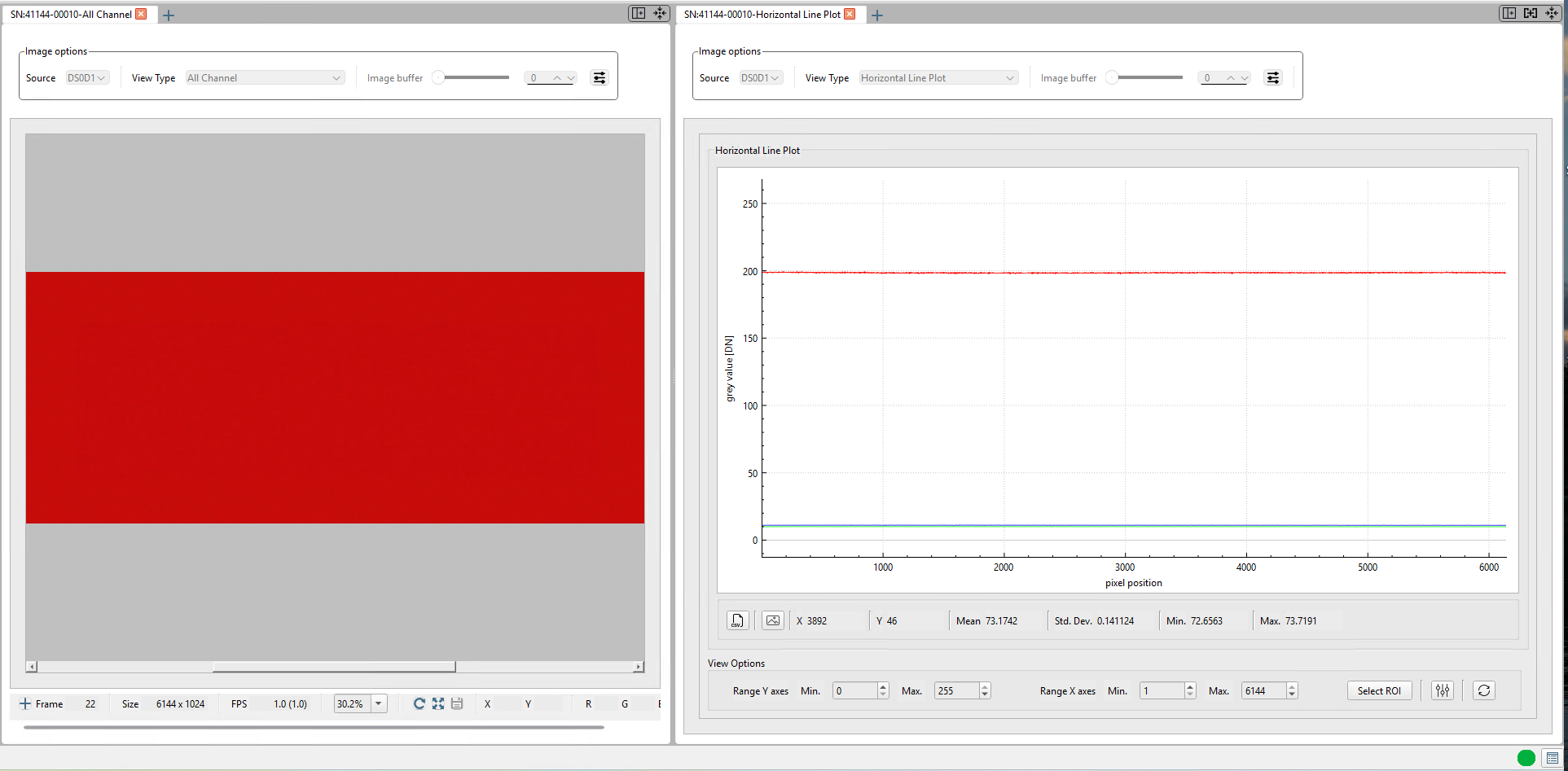
In this instance, the lighting arrangement is single-colored and is visible in the camera's red color channel. The signals in the green and blue channels are quite minimal. On the left of the image, you can observe the RGB image, while on the right, the profile of the horizontal line plot is displayed. In this scenario, the result of the PRNU calibration should be a RED image exhibiting a uniform profile. |
|
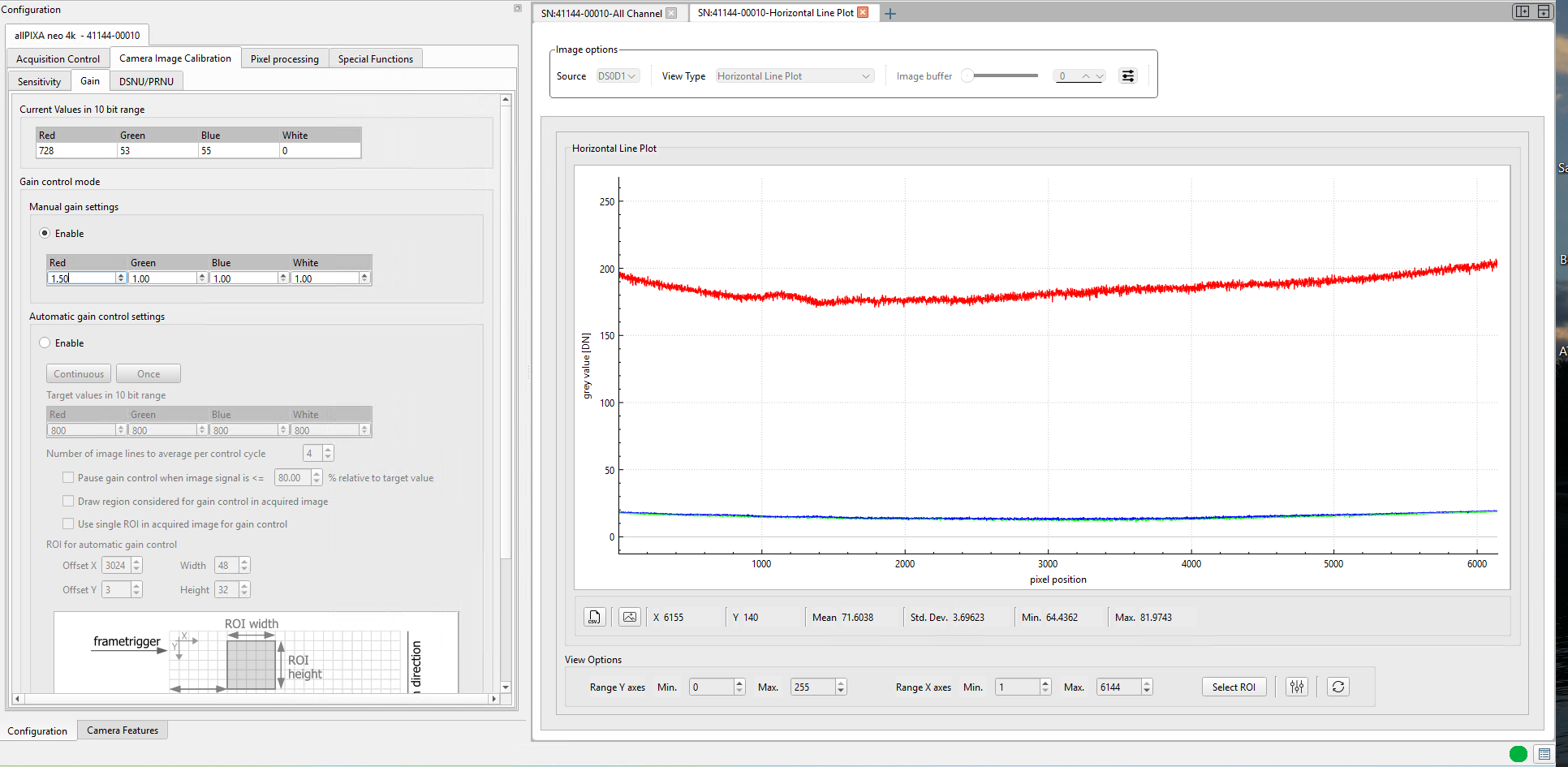
The "white balancing" process in the Independent calibration technique varies. The gain level needs to be modified for each specific gain. In this case, the Gain is solely applied to the Red channel. |
|
|
|
The Generate PRNU Reference wizard opens.
The raw image and the line plot of the image is displayed.
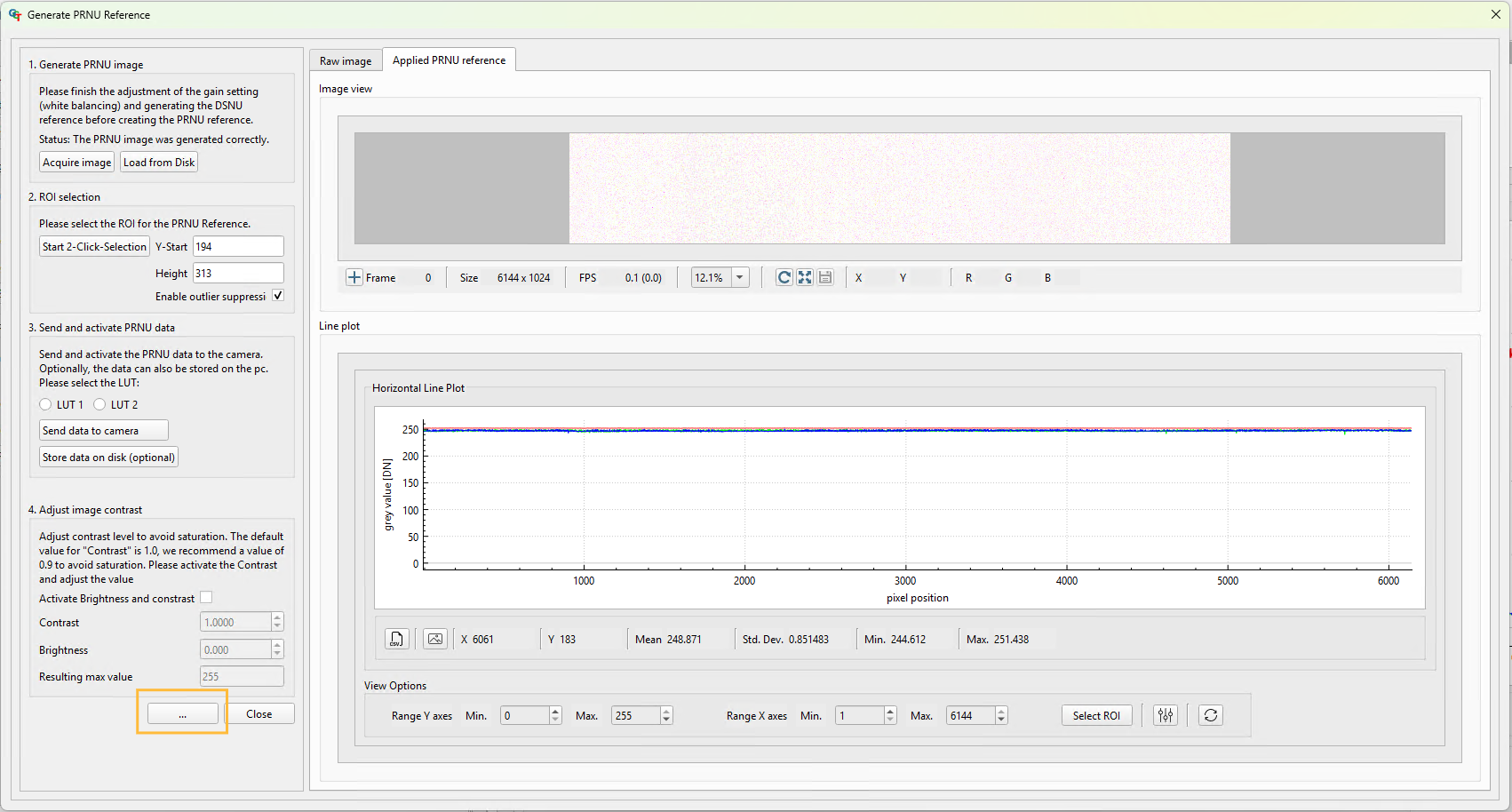
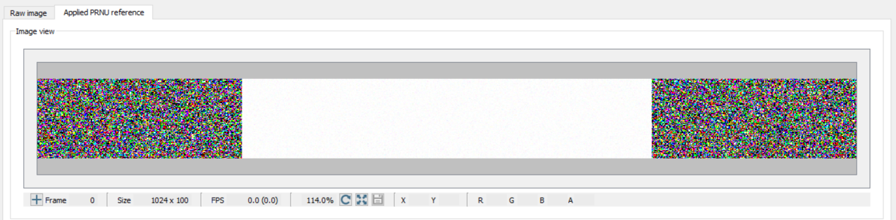
The view changed to the “Applied PRNU Reference”. This is the Output of the “Standard PRNU” Method. The image is very noisy.
| |
Send the calculated PRNU to the camera:
Activate brightness and contrast:
|
|
This image illustrates the results of the calibration process. It is a uniform image. |
|
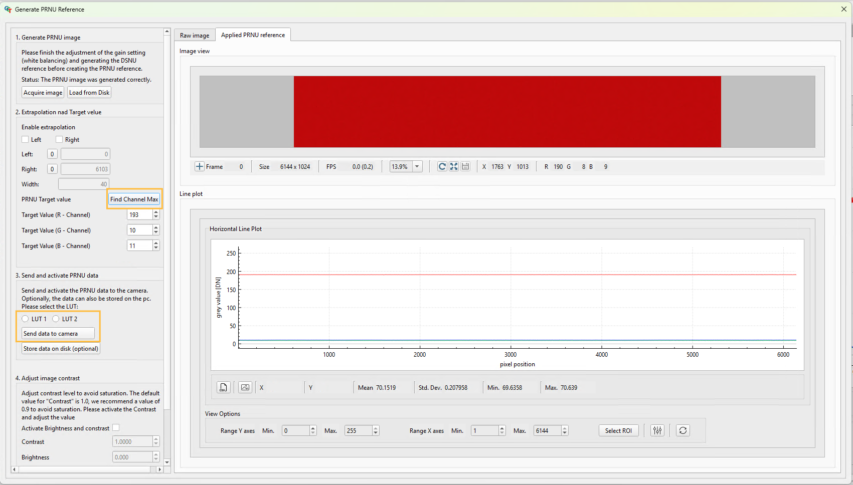
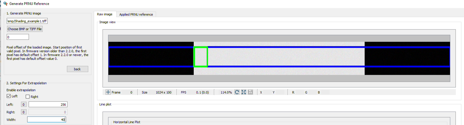
Extrapolation function
If the white reference does not cover the entire FOV, the extrapolation function can be used to generate it. In this case, a straight line is fitted to the gradient. Therefore follow the description below.
On the right side, you can see the raw image and the Applied PRNU reference without the extrapolation function. |
|
|
|
|
|
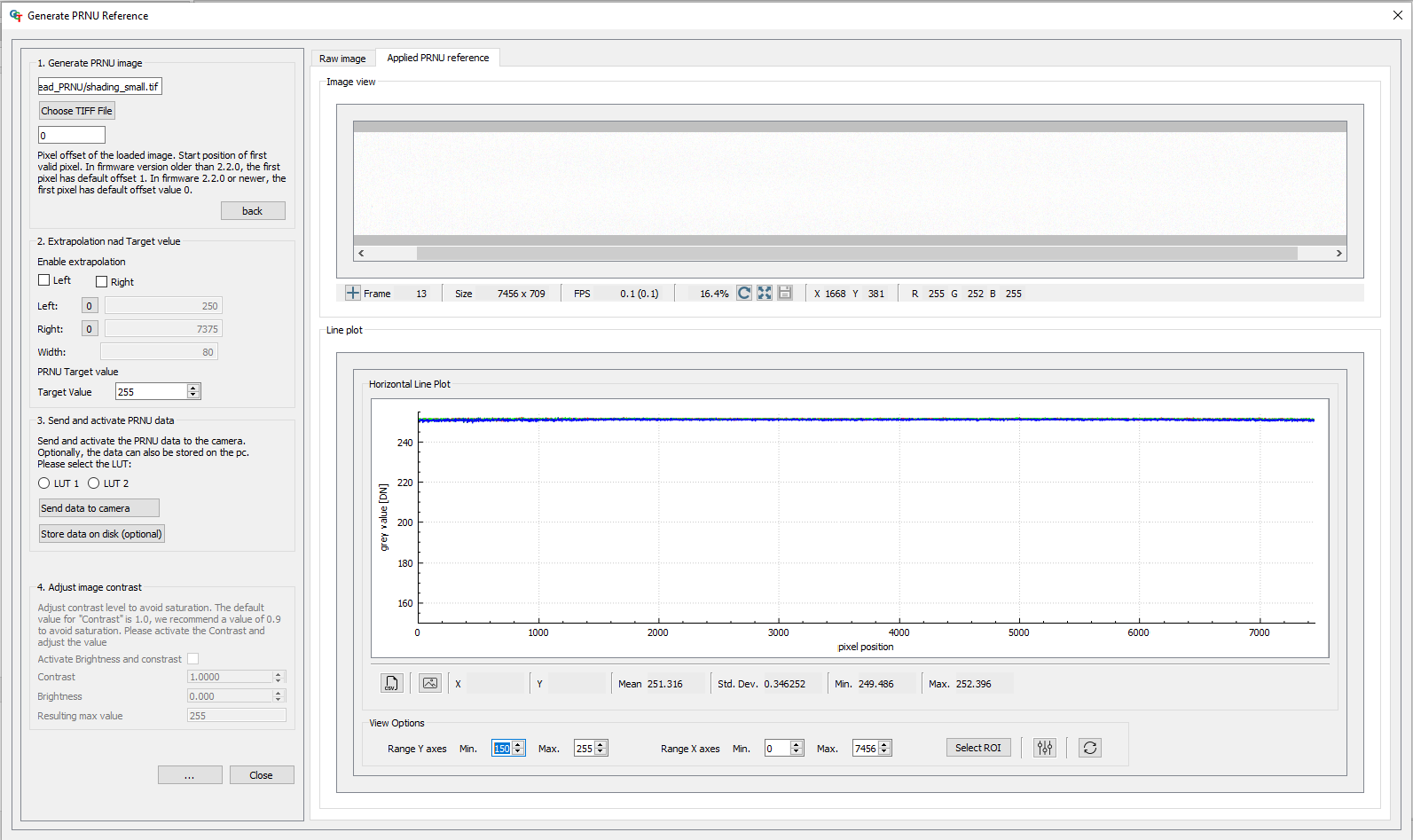
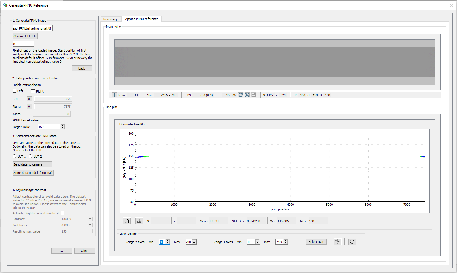
Target Value
The Target Value limits the maximum intensity of your CalibratedImage.
Note
Make sure that the Values of your PRNUImage are smaller than your TargetValue
1. Press the button with the three dots on the bottom. |
|
2. Change the Target Value. 3. Check the applied PRNU in the Applied PRNU reference tab. |
|