Camera specifications
| Sensor | CMOS line scan sensor, 16 lines (RGB, NIR-pass & mono) |
| Pixel size | 5.0 µm × 5.0 µm |
| Line spacing | 5 µm between R-G & G-B |
| Spectral sensitivity | 360 nm – 960 nm |
| Resolution | 8192 × 4 lines (16 lines available) |
| Video output | 4 × CoaXPress 2.0 |
| Data format | 3 × 8/10/12 Bit color or 1 × 8/10/12 Bit mono or 4 × 8/10/12 RGB + NIR |
| Trigger Mode | Frame Start / Frame Active / Line Start External trigger Line trigger / Encoder and Frame trigger |
| Video output port | 4 × CXP-12 Micro-BNC |
| Interface position | Y, Z |
| Digital I/O port | External I/O (15 pin HD D-Sub, fem.) |
| Power supply | 6 pin Hirose, male 12 V – 24 V DC ± 20 %; 1 A @ 24 V |
| Debugging port | USB 2.0 (Micro USB) |
| Lens mount / adapter | M72 × 0.75 mm / F-mount |
| Housing dimensions | 102 mm × 76 mm × 82 mm (W × H × D) |
| Weight | 0.9 kg |
| Temperature during operation | 0 °C – 60 °C; 32 °F – 140 °F |
| Humidity during operation | 20 % – 85 % relative air humidity, non condensing |
| Temperature during transport and storage | -20 °C – +85 °C; -4 °F – +185 °F |
| Protection category | IP50 |
| Certifications | CE, RoHS |
| General ambient conditions | |
| Transport | IEC 721-3-3:IE33 |
| Operation | IEC 721-3-3:IE21 |
| Storage | IEC 721-3-3:IE11 |
Line scan sensor
 The three different read modes and the sensor line spacing
Sensor pixel arrangement
Spectral sensitivity
.svg) Measured quantum efficiency of the 8k sensor
Measured quantum efficiency of the 8k sensor Sensor alignment and orientation
| Feature | Value |
|---|---|
| First pixel | Left side |
| Sensor position alignment | X: < ± 100 µm Y: < ± 100 µm Y: < ± 100 µm |
| Sensor rotation alignment | Y: < ± 0.1° Z: < ± 0.1° |
| Planarity of the sensor interface | < ± 0.5 µm |
| Sensor window thickness | 0.7 mm |
| Refraction index | 1.5 |
| Optical path extension | 0.35 mm |
Mechanical dimensions
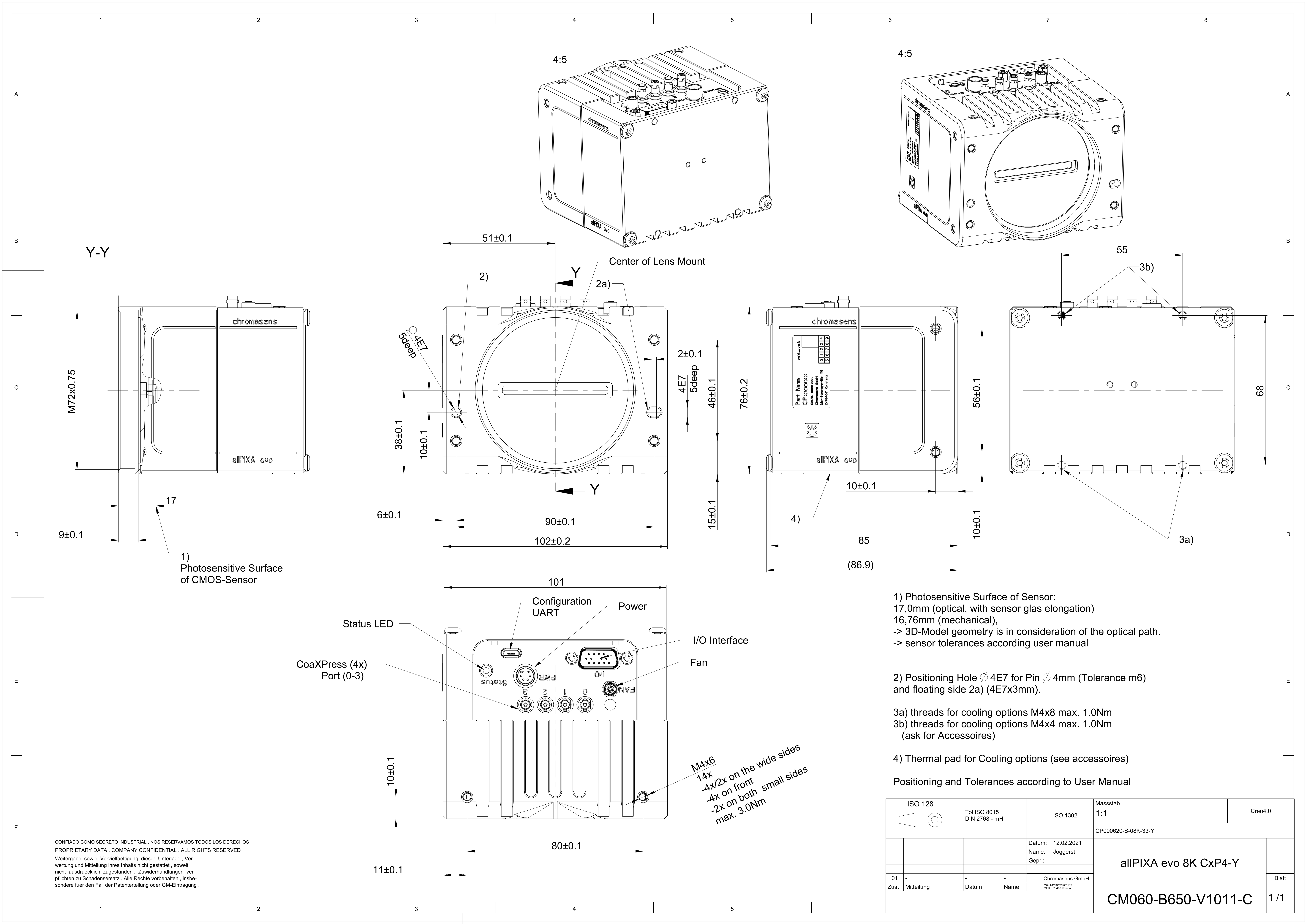 Dimensional drawing of the allPIXA evo 8k CXP – interface position Y
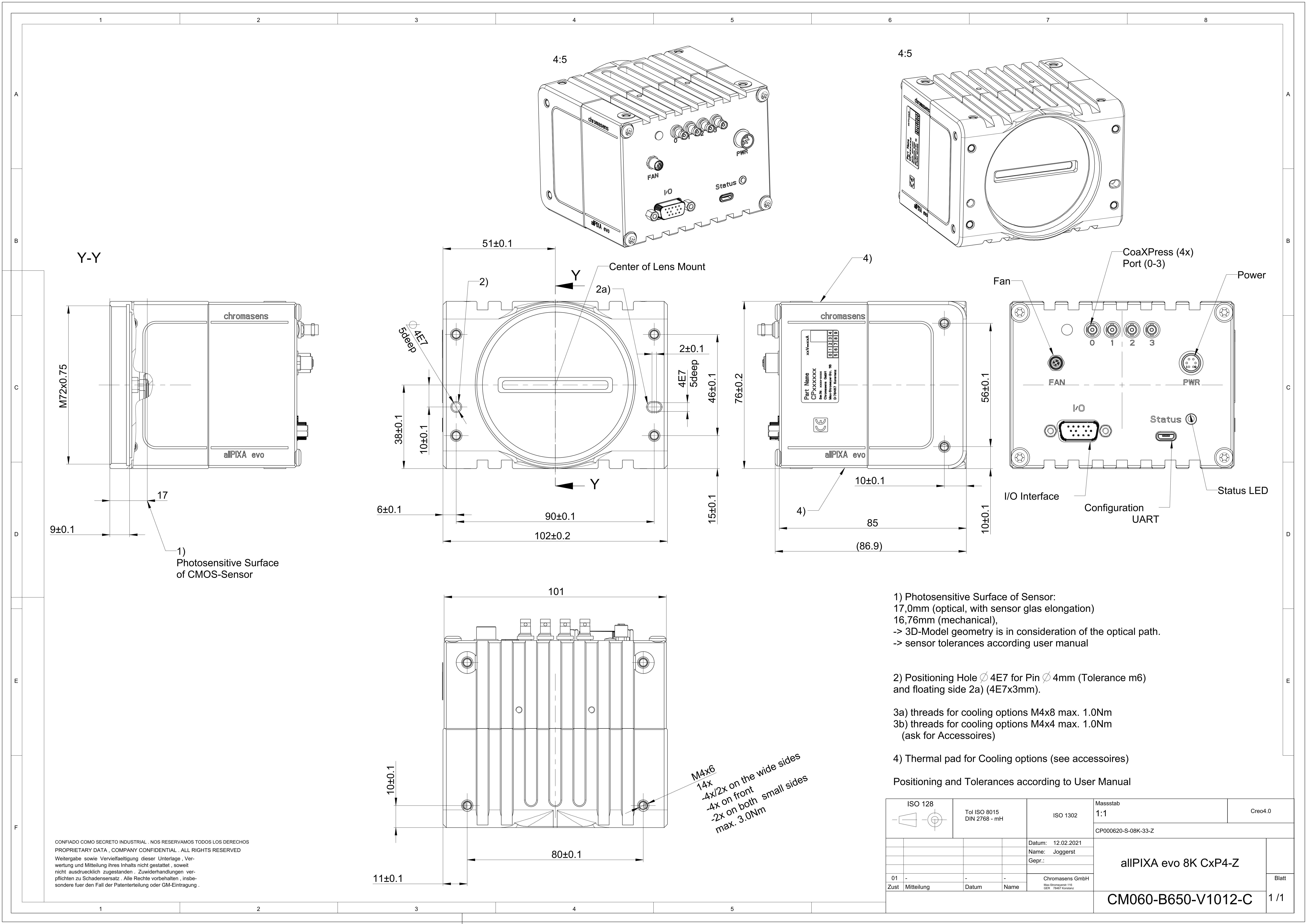 Dimensional drawing of the allPIXA evo 8k CXP – interface position Z
Download as pdf-file
Interface specification
 | |||
| 1 | Connector for additional fan | 2 | Video output port (4 × CoaXPress 2.0) |
| 3 | Power supply | 4 | Status LED |
| 5 | Debugging port | 6 | Digital I/O port |
| 7 | CXP Interface LED | ||
Line rate
| Configuration | CXP 12 one port (CXP12_X1) | CXP 12 two ports (CXP12_X2) | CXP 12 four ports (CXP12_X4) |
|---|---|---|---|
| RGB 8: 8,192 × 3 pixel | 43.2 kHz | 90.1 kHz | 100.0 kHz |
| RGB 10: 8,192 × 3 pixel | 20.7 kHz | 32.5 kHz | 90.1 kHz |
| RGB 12: 8,192 × 3 pixel | 20.7 kHz | 32.5 kHz | 90.1 kHz |
| RGBa 8: 8,192 × 4 pixel | 32.5 kHz | 68.2 kHz | 100.0 kHz |
| RGBa 10: 8,192 × 4 pixel | 15.6 kHz | 32.5 kHz | 68.2 kHz |
| RGBa 12: 8,192 × 4 pixel | 15.6 kHz | 32.5 kHz | 68.2 kHz |
| Mono 8: 8,192 × 1 pixel | 100.0 kHz | 100.0 kHz | 100.0 kHz |
| Mono 10: 8,192 × 1 pixel | 65.0 kHz | 100.0 kHz | 100.0 kHz |
| Mono 12: 8,192 × 1 pixel | 65.0 kHz | 100.0 kHz | 100.0 kHz |
Power supply
The following connector is required for the power supply cable:
- Manufacturer: Hirose
- Article no.: HR10A-7P-6S female
| Pin | Description | |
|---|---|---|
 Pin allocation of the power supply port Pin allocation of the power supply port
| 1 | Power +24 V |
| 2 | Power +24 V | |
| 3 | Not connected | |
| 4 | Not connected | |
| 5 | Ground | |
| 6 | Ground |
Digital I/O port
NOTE
Ensure a proper GND connection of the digital camera I/O port and your trigger.
The following connector is required for the digital I/O port:
- 15-pin HD D-Sub (male)
 Pin allocation D-Sub connector (female) of the camera
| Pin | GenICam | Signal | Level | In/Out | Example/Remark |
|---|---|---|---|---|---|
| 1 | Line 1 | Enc0_InP (+) | RS 422 | Differential input | Encoder0 or LineTrigger |
| 2 | Line 2 | Enc1_InP (+) | RS 422 | Differential input | Encoder1 or Frametrigger |
| 3 | Line 3 | IO_0P | LVCMOS | Input | single-ended |
| 4 | - | RT | RS 485 | - | - |
| 5 | Line 5 | IO_2P | LVCMOS | Out | LED-Out1 |
| 6 | Line 1 | Enc0_InN (-) | RS 422 | Differential input | Encoder0 |
| 7 | Line 2 | Enc1_InN (-) | RS 422 | Differential input | Encoder1 |
| 8 | Line 4 | IO_1N | LVCMOS | Input single-ended | Trigger or Master-Slave Cascaded |
| 9 | - | RTN | RS 485 | Out | To LightController XLC4 |
| 10 | Line 6 | IO_3 | LVCMOS | Out | LED-Out2 |
| 11 | - | GND | - | GND | - |
| 12 | Line 7 | IO_4_SDA | LVCMOS | Out | LED-Out3 |
| 13 | - | GND | GND | - | - |
| 14 | Line 9 | Master/Slave | LVCMOS | Bi-directional | Master/Slave |
| 15 | Line 8 | IO_5_SCL | LVCMOS | Out | LED-Out4 |
LVCMOS and RS422 levels
| I/O standard | V_IL | V_IH | V_OL | V_OH | ||
|---|---|---|---|---|---|---|
| V_min | V_max | V_min | V_max | V_max | V_min | |
| LVCMOS | –0.5 | 0.7 | 1.7 | 3.6 | 0.4 | 2.1 |
| RS422 | –6 | 0.8 | 2 | 6 | - | - |
 | NOTICE |
| Non compliance may cause irreparable damages to the device. | |
| The maximum input level of the LVCMOS is 3.6 V. Use a level converter if necessary (e.g. 74 LVC14). |
Micro USB
The Micro-USB connection is currently used for debugging information.
LED status indicator
CXP Interface LED
| Color code | Behaviour | Description |
|---|---|---|
 | Off | No power supply or the input voltage is out of range. |
 | Solid orange | The system is booting. |
 | Flash_1_1red | The device is powered but not connected (not applicable to a device reliant on PoCXP power). |
 | AlternateFlash_12_5 green/orange; shown for a minimum of 1s even if connection detection is faster | The Connection detection is in progress, PoCXP is active. |
 | Flash_12_5 orange; shown for a minimum of 1s even if connection detection is faster | The Connection detection is in progress, PoCXP is not in use. |
 | AlternateFlash_0_5 red/green | The device/host is incompatible, PoCXP is active. |
| AlternateFlash_0_5 red/orange | The device/host is incompatible, PoCXP is not in use. |
 | Solid red | PoCXP is over-current (host only). |
 | Solid green | The device/host is connected, but no data is transferred. |
 | Flash_1_ orange | The device/host is connected, waiting for event (e.g. trigger). |
 | Flash_12_5 green | The device/host is connected, data is being transferred. |
 | 500ms red pulse | Error during data transfer (e.g. CRC error, single-bit error) is detected. In case of multiple errors, there shall be at least two green Flash_12_5 pulses, before the next error is indicated. |
 | AlternateFlash_0_5 green/orange | A connection test packet is being sent. |
 | AlternateFlash_0_5 red/green/orange | The compliance test mode is enabled (device only). |
 | Flash_12_5 red | A system error (e.g. internal error) ocurred. |
Status LED
| Color code | Behaviour | Description |
|---|---|---|
| Off | No power supply or the input voltage is out of range. |
 | Blue continuous | The device is OK and provides image data. Between image gaps the LED is off. |
 | Green continuous | The device is in power-up mode. |
 | Green blinking | The device is OK and ready. |
 | Yellow continuous | Warning-state: The device is operational. |
 | Red continuous | Error-state: The device is not operational. |