Camera specifications
| Sensor | Tri-linear CMOS color line sensor |
| Pixel size | 5.6 µm × 5.6 µm |
| Line spacing | 5.6 µm between R-G & G-B |
| Spectral sensitivity | 360 nm – 960 nm |
| Resolution | 10240 pixels × 3 lines |
| Video output | Single/Dual 10GigE, GigE Vision® 2.0 compliant |
| Data format | 3 × 8/10/12 Bit color or 1 × 8/10/12 Bit mono |
| Trigger Mode | Frame Start / Frame Active / Line Start External trigger Line trigger / Encoder and Frame trigger |
| Video output port | 2 × SFP+ |
| Interface position | X |
| Digital I/O port | External I/O (15 pin HD D-Sub, fem.) |
| Power supply | 6 pin Hirose, male 12 V – 24 V DC ± 10 %; 1 A @ 24 V |
| Debugging port | USB 2.0 (Micro USB) |
| Lens mount / adapter | M72 × 0.75 mm / F-mount |
| Housing dimensions | 102 mm × 76 mm × 82 mm (W × H × D) |
| Weight | 0.9 kg |
| Temperature during operation | 0 °C – 60 °C; 32 °F – 140 °F |
| Humidity during operation | 20 % – 85 % relative air humidity, non condensing |
| Temperature during transport and storage | -20 °C – +85 °C; -4 °F – +185 °F |
| Protection category | IP50 |
| Certifications | CE, RoHS |
| General ambient conditions | |
| Transport | IEC 721-3-3:IE33 |
| Operation | IEC 721-3-3:IE21 |
| Storage | IEC 721-3-3:IE11 |
Line scan sensor
 Sensor line spacing
Sensor pixel arrangement
Spectral sensitivity
 Measured relative spectral sensitivity of the 10k and 15k sensor - color
 Measured relative spectral sensitivity of the 10k and 15k sensor - mono
Sensor alignment and orientation
| Feature | Value |
|---|---|
| First pixel | Left side |
| Sensor position alignment | X: < ± 100 µm Y: < ± 100 µm Y: < ± 100 µm |
| Sensor rotation alignment | Y: < ± 0.1° Z: < ± 0.1° |
| Planarity of the sensor interface | < ± 0.5 µm |
| Sensor window thickness | 1.1 mm |
| Refraction index | 1.5 |
| Optical path extension | 0.55 mm |
Mechanical dimensions
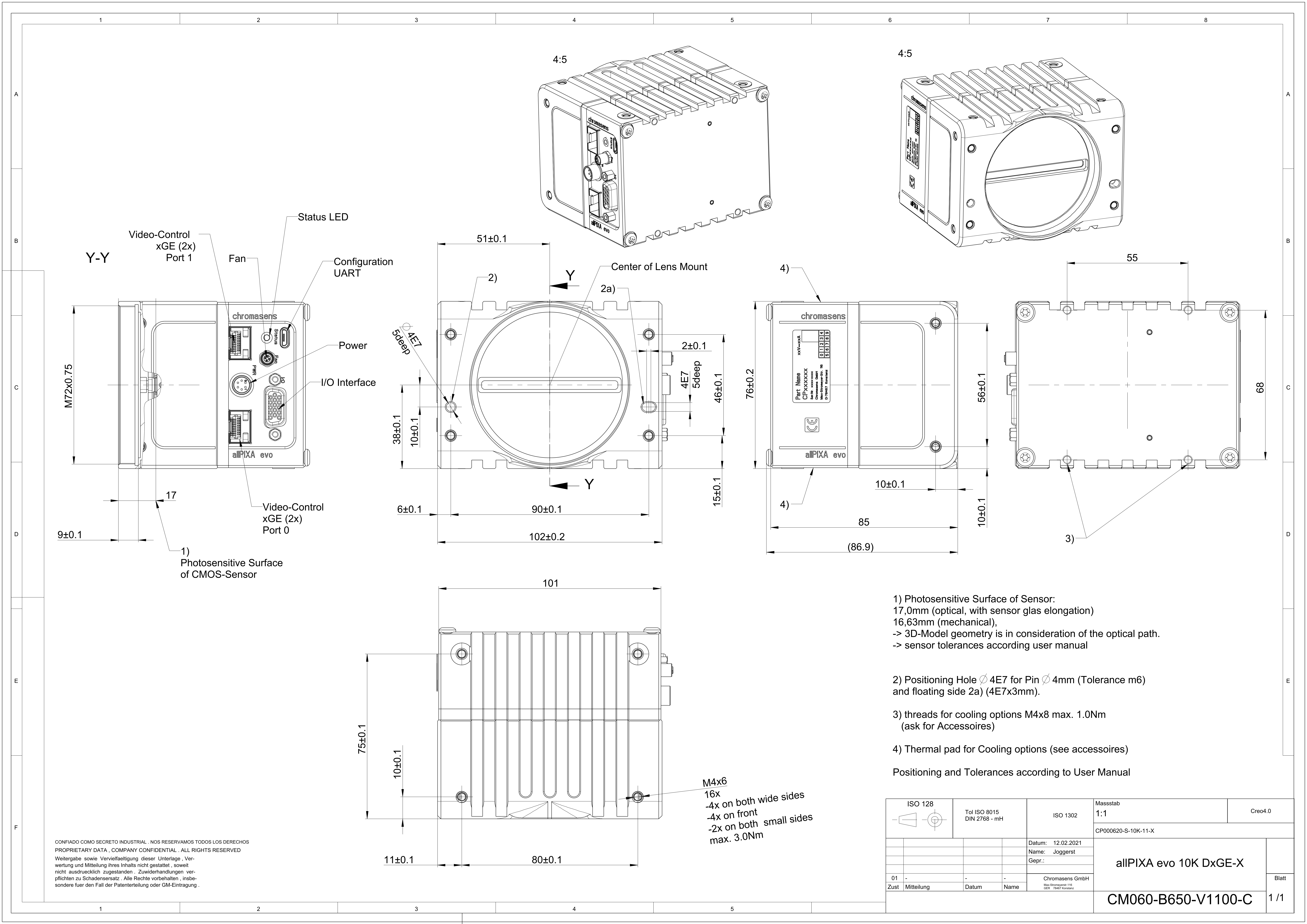
Dimensional drawing of the allPIXA evo 10k DXGE – interface position X
Download as pdf-file
Interface specification
 | |||
| 1 | Video output SFP+ port 1 (10GigE) | 2 | Status LED |
| 3 | Debugging port | 4 | Connector for additional fan |
| 5 | Power supply | 6 | Digital I/O port |
| 7 | Video output SFP+ port 2 (10GigE) | ||
Line rate
| Configuration | Single 10 GigE | Dual 10 GigE |
|---|---|---|
| RGB 8: 10,240 × 3 pixel | 38.5 kHz | 68.4 kHz |
| RGB 10: 10,240 × 3 pixel | 19.3 kHz | 34.7 kHz |
| RGB 12: 10,240 × 3 pixel | 19.3 kHz | 37.7 kHz |
| Mono 8: 10,240 × 1 pixel | 68.4 kHz | 68.4 kHz |
| Mono 10: 10,240 × 1 pixel | 57.4 kHz | 68.4 kHz |
| Mono 12: 10,240 × 1 pixel | 57.4 kHz | 68.4 kHz |
Power supply
The following connector is required for the power supply cable:
- Manufacturer: Hirose
- Article no.: HR10A-7P-6S female
| Pin | Description | |
|---|---|---|
 Pin allocation of the power supply port Pin allocation of the power supply port
| 1 | Power +24 V |
| 2 | Power +24 V | |
| 3 | Not connected | |
| 4 | Not connected | |
| 5 | Ground | |
| 6 | Ground |
Digital I/O port
NOTE
Ensure a proper GND connection of the digital camera I/O port and your trigger.
The following connector is required for the digital I/O port:
- 15-pin HD D-Sub (male)
 Pin allocation D-Sub connector (female) of the camera
| Pin | GenICam | Signal | Level | In/Out | Example/Remark |
|---|---|---|---|---|---|
| 1 | Line 1 | Enc0_InP (+) | RS 422 | Differential input | Encoder0 or LineTrigger |
| 2 | Line 2 | Enc1_InP (+) | RS 422 | Differential input | Encoder1 or Frametrigger |
| 3 | Line 3 | IO_0P | LVCMOS | Input | single-ended |
| 4 | - | RT | RS 485 | - | - |
| 5 | Line 5 | IO_2P | LVCMOS | Out | LED-Out1 |
| 6 | Line 1 | Enc0_InN (-) | RS 422 | Differential input | Encoder0 |
| 7 | Line 2 | Enc1_InN (-) | RS 422 | Differential input | Encoder1 |
| 8 | Line 4 | IO_1N | LVCMOS | Input single-ended | Trigger or Master-Slave Cascaded |
| 9 | - | RTN | RS 485 | Out | To LightController XLC4 |
| 10 | Line 6 | IO_3 | LVCMOS | Out | LED-Out2 |
| 11 | - | GND | - | GND | - |
| 12 | Line 7 | IO_4_SDA | LVCMOS | Out | LED-Out3 |
| 13 | - | GND | GND | - | - |
| 14 | Line 9 | Master/Slave | LVCMOS | Bi-directional | Master/Slave |
| 15 | Line 8 | IO_5_SCL | LVCMOS | Out | LED-Out4 |
LVCMOS and RS422 levels
| I/O standard | V_IL | V_IH | V_OL | V_OH | ||
|---|---|---|---|---|---|---|
| V_min | V_max | V_min | V_max | V_max | V_min | |
| LVCMOS | –0.5 | 0.7 | 1.7 | 3.6 | 0.4 | 2.1 |
| RS422 | –6 | 0.8 | 2 | 6 | - | - |
 | NOTICE |
| Non compliance may cause irreparable damages to the device. | |
| The maximum input level of the LVCMOS is 3.6 V. Use a level converter if necessary (e.g. 74 LVC14). |
Micro USB
The Micro-USB connection is currently used for debugging information.
LED status indicator
| Color code | Behaviour | Description |
|---|---|---|
 | Off | No power supply or the input voltage is out of range. |
 | Blue continuous | The device is OK and provides image data. Between image gaps the LED is off. |
 | Green continuous | The device is in power-up mode. |
 | Green blinking | The device is OK and ready. |
 | Yellow continuous | Warning-state: The device is operational. |
 | Red continuous | Error-state: The device is not operational. |