Camera specifications
General | |
Model | allPIXA evo 32K CXP mono Z allPIXA evo 32K CXP mono Y |
Product code | CP000620-S-32K-33-L1-M-Z CP000620-S-32K-33-L1-M-Y |
Availability | Available |
Sensor | |
Sensor type | Line scan 2D |
Chroma | Mono |
Spectrum | Visible-NIR |
Spectral range | 400-1000 nm |
Resolution | 32768 × 1 |
Sensor architecture | CMOS (Si) |
Sensor Size / Image circle | 82 mm |
Pixel size | 2.5 µm x 2.5 µm |
Pixel formats / Data format / Output color space | |
Data format | 1 × 8/10/12 Bit mono |
Sensor bit depth (ADC) | 12-bit |
Video output | 4 × CoaXPress 2.0 |
Imaging performance | |
Quantum efficiency (529 nm) | |
Quantum efficiency (850 nm) | |
Timing and gain | |
Max. line rate (single-line) | 73 kHz |
Exposure time | |
Gain | |
I/O’s and Power | |
Non-isolated lines (external/housing) (I/O’s) | 7 BiDir LVCMOS 3V3 |
Non-isolated lines (internal for OEM) | 2 BiDir LVCMOS 3V3 (Master/Slave) 1 LVCMOS RS232 2 BiDir LVCMOS 3V3 (LED-CTRL) |
Specific non-isolated lines (I/O’s) | 1 RS485 1 µUSB (UART) 2RS422-In 1 FAN 24V +CLK |
Opto-isolated lines( I/O’s) | 0 |
I/O connector | External I/O (15 pin HD D-Sub, fem.) |
Power supply | 12 to 24 VDC, PoCXP |
Power consumption | External: 24 W |
Power connector | 6 pin Hirose, male |
Operating conditions | |
Operating temperature (housing) | 0 °C – 60 °C; 32 °F – 140 °F |
Mechanical properties | |
Body dimensions (L x W x H) | 102 mm x 102 mm x 113 mm |
Filter / Protection glass | - |
IP class (ingress protection) | IP50 |
Shock and vibration tests | |
Lens mount | M95 × 1 mm |
Weight / Mass | 1.1 kg |
On-board memory on FPGA | |
Image buffer (RMA) | none |
Non-volatile memory (Flash) | 256 Mbit |
User data memory | No separate memory space |
Interface for image transfer | |
Digital interface / Video output | CXP-12 with 4 Connections |
Interface connector | Micro-BNC |
Vision standard | CoaxPress |
Interface position | Z |
Humidity during operation | 20 % – 85 % relative air humidity, non condensing |
Temperature during transport and storage | -20 °C – +85 °C; -4 °F – +185 °F |
Certifications | CE, RoHS |
General ambient conditions | |
Transport | IEC 721-3-3:IE33 |
Operation | IEC 721-3-3:IE21 |
Storage | IEC 721-3-3:IE11 |
Camera features
Image control | |
Binning | Digital |
Color transformation | No |
Brightness and Contrast | Yes |
Exposure modes | Manual |
PRNU | Yes |
DSNU | Yes |
Gain modes | Manual Auto |
Gamma | Yes |
LUT (look-up table) | Yes |
Mirror Images | Yes |
ROI (region of interest) | Yes |
White balance mode | Manual Auto |
Camera control | |
Acquisition Line Rate | Yes |
Action commands (Trigger over CXP) | Yes |
Temperature monitoring | Yes |
Trigger mods / sync | Freerun Internal Software trigger External trigger Line trigger Frame trigger Encoder Trigger over CXP |
User sets | Yes |
Master Slave | Yes |
Flash (Multi field imaging) | Yes |
Sensor temperature control | |
Temperature specific events | Yes |
Temperature status indicator | Yes |
Line scan sensor
Sensor pixel arrangement
Spectral sensitivity
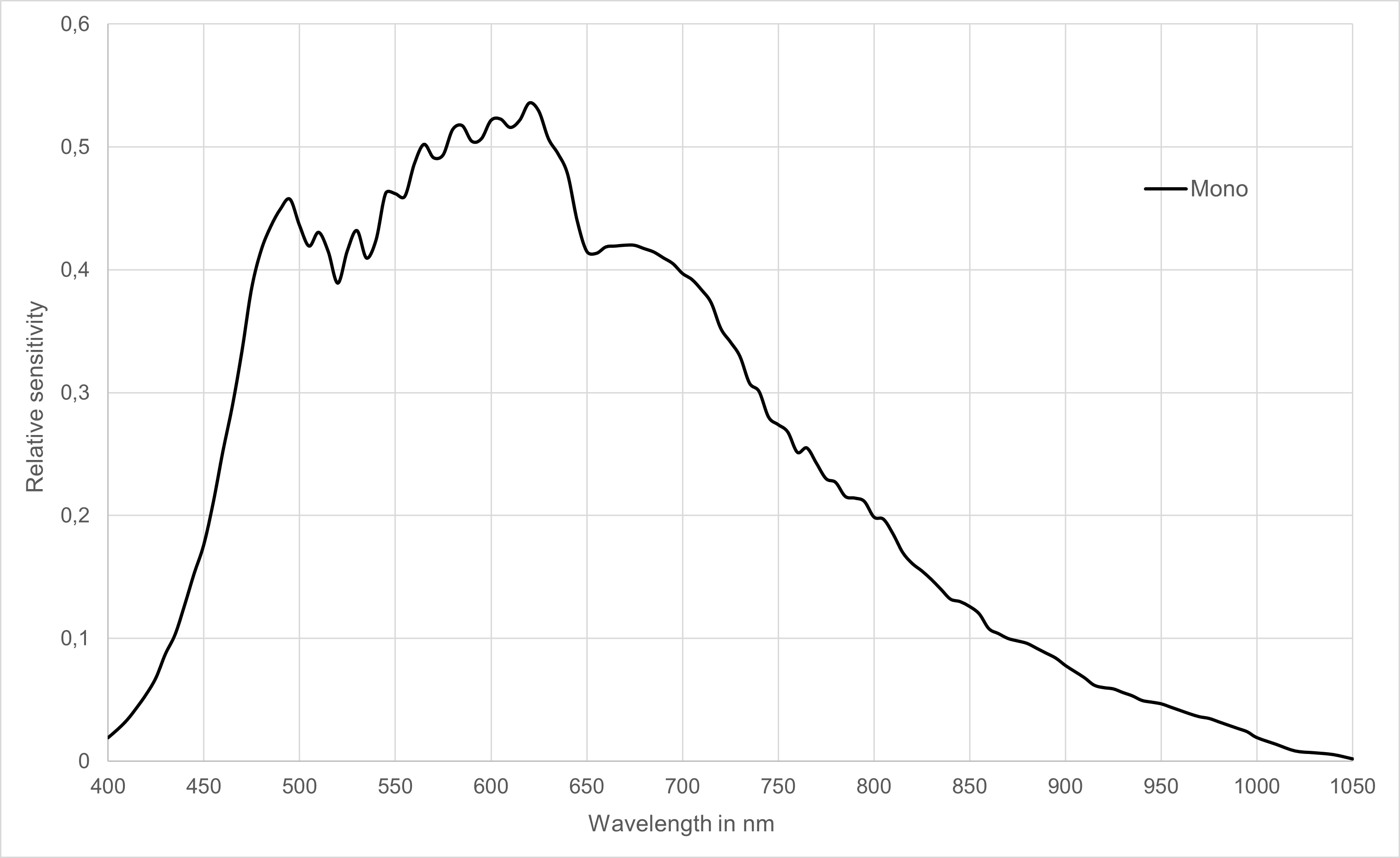 Relative spectral sensitivity of the camera
Sensor alignment and orientation
Mechanical dimensions
.PNG)
Dimensional drawing of the allPIXA evo 32k CXP - interface position Z
Download as pdf-file
Dimensional drawing of the allPIXA evo 32k CXP – interface position Z
Interface specification
 | |||
| 1 | Connector for additional fan | 2 | Video output (4 × CoaXPress 2.0) |
| 3 | Power supply | 4 | Status LED |
| 5 | Debugging port | 6 | Digital I/O port |
| 7 | CXP Interface LED | ||
Power supply
The following connector is required for the power supply cable:
- Manufacturer: Hirose
- Article no.: HR10A-7P-6S female
| Pin | Description | |
|---|---|---|
 Pin allocation of the power supply port Pin allocation of the power supply port
| 1 | Power +24 V |
| 2 | Power +24 V | |
| 3 | Not connected | |
| 4 | Not connected | |
| 5 | Ground | |
| 6 | Ground |
Digital I/O port
The following connector is required for the digital I/O port:
- 15-pin HD D-Sub (male)
 Pin allocation D-Sub connector (female) of the camera
| Pin | GenICam | Signal | Level | In/Out | Example/Remark |
|---|---|---|---|---|---|
| 1 | Line 1 | Enc0_InP (+) | RS 422 | Differential input | Encoder0 or LineTrigger |
| 2 | Line 2 | Enc1_InP (+) | RS 422 | Differential input | Encoder1 or Frametrigger |
| 3 | Line 3 | IO_0P | LVCMOS | Input | single-ended |
| 4 | - | RT | RS 485 | - | - |
| 5 | Line 5 | IO_2P | LVCMOS | Out | LED-Out1 |
| 6 | Line 1 | Enc0_InN (-) | RS 422 | Differential input | Encoder0 |
| 7 | Line 2 | Enc1_InN (-) | RS 422 | Differential input | Encoder1 |
| 8 | Line 4 | IO_1N | LVCMOS | Input single-ended | Trigger or Master-Slave Cascaded |
| 9 | - | RTN | RS 485 | Out | To LightController XLC4 |
| 10 | Line 6 | IO_3 | LVCMOS | Out | LED-Out2 |
| 11 | - | GND | - | GND | - |
| 12 | Line 7 | IO_4_SDA | LVCMOS | Out | LED-Out3 |
| 13 | - | GND | GND | - | - |
| 14 | Line 9 | Master/Slave | LVCMOS | Bi-directional | Master/Slave |
| 15 | Line 8 | IO_5_SCL | LVCMOS | Out | LED-Out4 |
LVCMOS and RS422 levels
| I/O standard | V_IL | V_IH | V_OL | V_OH | ||
|---|---|---|---|---|---|---|
| V_min | V_max | V_min | V_max | V_max | V_min | |
| LVCMOS | –0.5 | 0.7 | 1.7 | 3.6 | 0.4 | 2.1 |
| RS422 | –6 | 0.8 | 2 | 6 | - | - |
 | NOTICE |
| Non compliance may cause irreparable damages to the device. | |
| The maximum input level of the LVCMOS is 3.6 V. Use a level converter if necessary (e.g. 74 LVC14). |
Micro USB
The Micro-USB connection is currently used for debugging information.
LED status indicator
CXP Interface LED
| Color code | Behaviour | Description |
|---|---|---|
 | Off | No power supply or the input voltage is out of range. |
 | Solid orange | The system is booting. |
 | Flash_1_1red | The device is powered but not connected (not applicable to a device reliant on PoCXP power). |
 | AlternateFlash_12_5 green/orange; shown for a minimum of 1s even if connection detection is faster | The Connection detection is in progress, PoCXP is active. |
 | Flash_12_5 orange; shown for a minimum of 1s even if connection detection is faster | The Connection detection is in progress, PoCXP is not in use. |
 | AlternateFlash_0_5 red/green | The device/host is incompatible, PoCXP is active. |
| AlternateFlash_0_5 red/orange | The device/host is incompatible, PoCXP is not in use. |
 | Solid red | PoCXP is over-current (host only). |
 | Solid green | The device/host is connected, but no data is transferred. |
 | Flash_1_ orange | The device/host is connected, waiting for event (e.g. trigger). |
 | Flash_12_5 green | The device/host is connected, data is being transferred. |
 | 500ms red pulse | Error during data transfer (e.g. CRC error, single-bit error) is detected. In case of multiple errors, there shall be at least two green Flash_12_5 pulses, before the next error is indicated. |
 | AlternateFlash_0_5 green/orange | A connection test packet is being sent. |
 | AlternateFlash_0_5 red/green/orange | The compliance test mode is enabled (device only). |
 | Flash_12_5 red | A system error (e.g. internal error) ocurred. |
Status LED
| Color code | Behaviour | Description |
|---|---|---|
| Off | No power supply or the input voltage is out of range. |
 | Blue continuous | The device is OK and provides image data. Between image gaps the LED is off. |
 | Green continuous | The device is in power-up mode. |
 | Green blinking | The device is OK and ready. |
 | Yellow continuous | Warning-state: The device is operational. |
 | Red continuous | Error-state: The device is not operational. |