GigE interface
The 10 GigE connectors permit to use (direct attach) copper cables with lengths of up to 30 m (10BASE-T). A cable with the minimum specification of CAT6a must be used.
Network adapter
To establish a 10 GigE connection a network adapter with a 10 GigE RJ45 input must be installed and configured on the PC. The installation of the network adapter is explained in the GCT documentation. For more information, see Installation GigE.
For more information about the tested network adapters and the transceivers, see Tested Network adapters and Transceivers.
Cabling
 | .png) WARNING WARNING |
| Electric shock due to improper connection to a power supply. | |
| Use a 12 V – 24 V DC power supply. When using the digital I/O port as a power supply ensure the correct polarity. |
Connect the video output port.
Connect the digital I/O port.
Option 1: Power over Ethernet (PoE)
1. Plug the Ethernet cable into the Power/PoE port (PoEOUT) of the PoE injector and into the video output port (RJ45) of your camera.
2. Connect another Ethernet cable to the Ethernet/data (DataIN) port of the injector and your network card.
Option 2: Power supply of the digital I/O port
To set up the wiring refer to section Digital I/O port.
Note the permitted input voltages:
Nominal | Minimum | Maximum | |
|---|---|---|---|
Permitted voltages | 24 V | 12 V | 28 V |
CXP interface
The interface allows you to connect two CXP cables. Micro BNC (for CXP12) connectors for the camera and suitable connectors for the frame grabber are required. The maximum cable length is 35 m.
Frame grabber
To establish a CXP connection a frame grabber must be installed and configured on the PC. Refer to the manual of your frame grabber.
For more information about the tested frame grabbers, see Tested frame grabbers.
Cabling
| WARNING |
| Electric shock due to improper connection to a power supply. | |
| Use a 12 V – 24 V DC power supply. When using the digital I/O port as a power supply ensure the correct polarity. |
Connect the video output port.
Connect the digital I/O port.
Option 1: Power over CoaXPress (PoC)
To use the power-over-CXP function two connections are needed.
Option 2: Power supply of the digital I/O port
To set up the wiring refer to section Digital I/O port.
Note the permitted input voltages:
Nominal | Minimum | Maximum | |
|---|---|---|---|
Permitted voltages | 24 V | 12 V | 28 V |
Digital I/O port
The following connector is required for the digital I/O port:
- 15 pin HD D-Sub (female)
 Pin allocation D-Sub connector (male) of the camera
You can configure the digital I/O port as RS422 or as single-ended input or output. It is also possible to configure one output as RS422 and the other output as single-ended.
RS422 configuration
| Pin | Line definition for RS422 configuration | Signal RS422 | Configuration proposal |
|---|---|---|---|
| 1 | Line 1 | In1+ | Encoder Source A, Line Start |
| 2 | In1– | Encoder Source A\, Line Start\ | |
| 3 | Line 2 | In2+ | Encoder Source B, Fame Start, Frame Active |
| 4 | In2– | Encoder Source B\, Fame Start\, Frame Active\ | |
| 5 | GND (Signals) | Signals Ground | |
| 6 | Line 3 | In3+/Out3+ | Encoder Source A, Fame Start, Frame Active, Line Start, User Output3+ |
| 7 | In3–/Out3– | Encoder Source A\, Fame Start\, Frame Active\, Line Start\, User Output3- | |
| 8 | Line 4 | In4+/Out4+ | Encoder Source A, Fame Start, Frame Active, Line Start, User Output4+, MS-In+ |
| 9 | In4–/Out4– | Encoder Source A\, Fame Start\, Frame Active\, Line Start\, User Output4-, MS-In- | |
| 10 | GND (PWR) | Camera Power Ground | |
| 11 | Line 5 | Out5+ | User Output5+, MS-Out+ |
| 12 | Out5– | User Output5-, MS-Out- | |
| 13 | Line 6 | Out6+ | User Output6+ |
| 14 | User Output6- | ||
| 15 | Vcc (PWR) | Camera Power DC +12 V – +24 V |
Single-Ended (SE) configuration
The input threshold voltage can be configured globally to 3.3 V, 5 V, 12 V and 24 V. The Maximum input voltage is 28 V. The set voltage level is then active for all single ended inputs and outputs.
| Pin | Line definition for Single-Ended configuration | Signal Single-Ended | Configuration proposal |
|---|---|---|---|
| 1 | Line 1 | In1 (3.3 V, 5 V, 12 V, 24 V) | Encoder Source A, Line Start |
| 2 | -- | -- | -- |
| 3 | Line 2 | In2 (3.3 V, 5 V, 12 V, 24 V) | Encoder Source B, Fame Start, Frame Active |
| 4 | -- | -- | -- |
| 5 | GND (Signals) | Signals Ground | |
| 6 | Line 3 | In3 (3.3 V, 5 V, 12 V, 24 V) Out3 (3.3 V) | Encoder Source A, Fame Start, Frame Active, Line Start, User Output3+ |
| 7 | -- | -- | -- |
| 8 | Line 4 | In4 (3.3 V, 5 V, 12 V,24 V) Out4 (3.3 V) | Encoder Source A, Fame Start, Frame Active, Line Start, User Output4+ |
| 9 | -- | -- | -- |
| 10 | GND (PWR) | Camera Power Ground | |
| 11 | Line 5 | In5 (3.3 V) Out5 (3.3 V) | LED Flash Out 3, User Output5 |
| 12 | Line 7 | In7 (3.3 V) Out7 (3.3 V) | LED Flash Out 2, User Output7 |
| 13 | Line 6 | In6 (3.3 V) Out6 (3.3 V) | LED Flash Out 0, User Output6 |
| 14 | Line 8 | In8 (3.3 V) Out8 (3.3 V) | LED Flash Out 1, User Output8 |
| 15 | Vcc (PWR) | Camera Power DC +12 V – +24 V |
The Datasheet of I/O Cable CP000722-X and its internal color configuration can be found here: Datasheet CP000722.
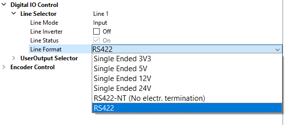
Configure the I/O's
The IO Ports can be configured in GCT.
1. Connect and open the camera in GCT | |
2. Navigate to Camera Features, Digital IO Control | |
3. Select the Line in the Line Selector | |
4. Open the Drop-down menu and change the Line Format |
|
Circuit Diagrams
RS422 configuration
 External circuit: RS422 device
Single-Ended configuration
 External circuit: Optocoupler
 External circuit: TTL or CMOS logic gate
Power supply
To set up the wiring refer to section Digital I/O port.
Note the permitted input voltages:
Nominal | Minimum | Maximum | |
|---|---|---|---|
Permitted voltages | 24 V | 12 V | 28 V |
The input current is 0.5 A @ 24 V.