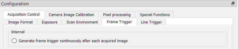
Internal frame trigger
The internal frame trigger provides a continuous signal after each acquired image.
In the Configuration window navigate to Acquisition Control → Frame Trigger.
Below Internal select the Generate frame trigger continuously after each acquired image checkbox.
Internal frame trigger
Alternatively, you can set the internal frame trigger in the camera feature tree by executing the following steps:
Step | Feature name | Value |
|---|---|---|
1 | Trigger Selector | FrameActive |
2 | Trigger Mode | Off |
3 | Trigger Selector | FrameStart |
4 | Trigger Mode | Off |
5 | Trigger Selector | LineStart |
6 | Trigger Mode | Off |
External frame trigger
The external frame trigger can be provided by a light barrier.
In the Configuration window navigate to Acquisition Control → Frame Trigger.
Below External select the Use external source to generate frame trigger checkbox.
|
|
.PNG)
Alternatively, you can set the external frame trigger in the camera feature tree by executing the following steps:
Step | Feature name | Value |
|---|---|---|
1 | TriggerSelector | FrameStart, FrameActive, FrameBurstStart, FrameBurstActive or FrameEnd |
TriggerMode | On | |
2 | TriggerSource | e.g. Line 3 or Line 4 |
3 | TriggerActivation | Level high/level low, |
4 | TriggerDelayLines | <number of lines> |
5 | TriggerSignalDetectionMode | Peakholder Detection, |
5 | Digital I/O Line Selector | select the Trigger Source |
6 | Line Format | open the Drop-down menu and change the Line Format to your input signal |
Trigger Selector
Frame start
The Trigger Selector → Frame start triggers the image acquisition after the Trigger delay lines and depending on the Trigger signal detection mode configuration for the duration of the image height setting. One frame trigger creates one image with a constant image height.

Input signal activation: Frame start
Frame active
Note
This configuration is only for the GigE Version available. CxP does not support this configuration.
The Trigger Selector → Frame active triggers the image acquisition after the Trigger delay lines and depending on the Trigger signal detection mode configuration for the duration of the Trigger signal. One Frame trigger creates one image with the length of the frame active signal.

Input signal activation: Frame active
Frame burst start
Note
In Frame burst start mode the camera acquires multiple gapless images.
The Trigger Selector → Frame burst start triggers the image acquisition after the Trigger delay lines and depending on the Trigger signal detection mode configuration for multiple times the duration of the image height setting. One frame burst creates multiple images with a constant image height.
The number of acquired images is set under Acquisistion Control → Acquisistion Burst Frame Count.

Input trigger activation: Frame burst start
Frame burst active
The Trigger Selector → Frame burst active triggers the image acquisition after the Trigger delay lines and depending on the Trigger signal detection mode configuration as long as the signal is high. For example, when a short input trigger signal is utilized, just two frames are acquired, while a more extended trigger signal leads to the capture of five or six frames.
This function also requires a Frame End signal ON, the Trigger Source could be the Frame Burst Active Source End or an external Line (IO).
.png)
Input trigger activation: Frame burst active
XX
Trigger activation
The TriggerActivation specifies the activation mode of the trigger.
Name | Description | Notes |
RisingEdge | Specifies that the trigger is considered valid on the rising edge of the source signal. | This enum entry is valid and available only for LineStart or FrameStart or FrameBurstStart |
FallingEdge | Specifies that the trigger is considered valid on the falling edge of the source signal. | This enum entry is valid and available only for FrameStart or FrameBurstStart |
LevelHigh | Specifies that the trigger is considered valid if the level of the source signal is high. | This enum entry is valid and available only for FrameActive |
LevelLow | Specifies that the trigger is considered valid if the level of the source signal is low. | This enum entry is valid and available only for FrameActive |
Frame Start | Frame Burst Start | Frame Active |
|
|
|
Trigger Source
The TriggerSource specifies the input line to use as a trigger source, please refer to the electrical installation.
Trigger signal detection mode
The camera supports four different Trigger signal detection modes. This configuration parameter defines the signal debouncing of the frame trigger input signal.
To set the Trigger signal detection navigate to the camera feature tree → Acquisition control → Trigger selector the following four options are available:
PeakholderDetection
The Trigger signal detection mode → PeakholderDetection detects every small input signal and starts the image acquisition immediately.

PeakholderDetection
Debouncing4Lines
The Trigger signal detection mode → Debouncing4Lines requires a 4-line stable trigger input signal, this leads to an image delay of 4 lines.

Debouncing4Lines
Debouncing60Lines
The Trigger signal detection mode → Debouncing60Lines requires a 60 line stable trigger input signal, leading to an image delay of 60 lines.

Debouncing60Lines
Debouncing4Clocks (not recommended)
The Trigger signal detection mode → Debouncing4Clocks requires a 4 clocks (clks) stable trigger input signal, leading to an image delay of 4 clocks.

Debouncing4Clocks
Trigger Delay Lines
Specifies the delay in the number of lines to apply after the trigger reception before activating it.
Line Format
The Digital IO Control → Line Selector → Line Format controls the electrical format of the selected physical input. For the specific electrical format, please refer to the electrical installation.
| Name | Description |
| NoConnect | The line is not connected. |
| SingleEnded_3V3 | The line is single ended input or output for 3.3V. Input signals less than 1.5V are considered as level low, signals higher than 1.5V as level high. |
| SingleEnded_5 | The line is single ended input for 5.0V or output for 3.3V. Input signals less than 2.5V are considered as level low, signals higher than 2.5V as level high. |
| SingleEnded_12V | The line is single ended input for 12.0V or output for 3.3V. Input signals less than 5.0V are considered as level low, signals higher than 5.0V as level high. |
| SingleEnded_24V | The line is single ended input for 24.0V or output for 3.3V. Input signals less than 5.0V are considered as level low, signals higher than 5.0V as level high. |
| RS422_NoTerm | The line is currently accepting or sending RS422 level signals with no electrical termination. |
| RS422 | The line is currently accepting or sending RS422 level signals. |
| Misc | The line is a special one. |