Check the installation position of the allPIXA camera with lens, alignment adapter and illumination. Control the distance from allPIXA Alignment Adapter/Camera to target.
| |
Check the adjustment target: is it placed in the correct position, is it clean and flat.
| |
Switch on the corona illumination with XLC4 Commander.
| |
Check for correct aligned illumination to target.
| |
Connect the allPIXA camera to the GCT and Acquire Images. If the target is not visible, please check the alignment of the components, the brightness of the illumination or the exposure timer of the camera Note: The adjustment target is acquired in free running mode.
| |
Open GCT2 Click in Tools → Perform Adjustment.
| |
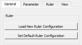
Click in the Adjustment Tool Load New Ruler Configurator. Select AdjustParameterDescription.json File. Select AdjustRulerDescription.json File.
| |
Select Start Scanning Images for continues scan (recommended) or Start Single Scan for capturing only one image. Note: Load Image and Save Image serves for documentation and comparison of other adjusted systems.
| |
The Target is now shown in the stream. The ROI markers at the top of the screen show the relevant searching area. Note: This degree of freedom is determined by the screw-on position of the alignment adapter itself, a larger offset can only be corrected by moving the complete alignment adapter
| |
The Adjustment Software enables you to adjust limit parameters as well as safety thresholds, for more information please refer to Parameter
| |
For orientation and coordinate system for the following adjustment process, please refer to Technical Drawing allPIXA Alignment Adapter.
| |
Check delta X and adjust delta Y Note: Delta X is determined by the screw-on position of the alignment adapter itself, a larger offset can only be corrected by moving the complete alignment adapter. Delta Y is adjusted by the dY Screw. The magenta frame indicates the region of correct adjustment. This frame is getting bigger when the alignment is moving in the correct direction. if the Frame is getting smaller in size the misalignment is getting larger. Limits in Pixel for Delta X and Delta Y can be set in Parameter.
| |
Check Rot-Z Rot-Z adjusted by the Rot-Z Screw.
Limits for Angle in degree can be set in Parameters. | |
Check Deviation of optical Resolution The deviation indicates the error of the optical target resolution as a percentage. The information on the resolution deviation of the left and right half of the image is given, resulting in an mean resolution deviation. The resolution must be adjusted over the distances from the scan plane to the lens and sensor plane, for example using a modular focus. If there are major deviations, the installation position of the camera, lens and the distances of the scan plane must be verified.
| |
Re-check the Y and X position. Due to the dependencies of individual parameters, the previously set adjustment must a be checked iteratively and readjusted if necessary.
| |
Adjusting to the optimum focus level The optimum focus level is set via dZ, which adjusts the Z- position of the camera. The Modulation values for the left, middle and right image area are displayed. The goal is to generate a maximum of the Modulation values.
The maximum MTF values achieved in the adjustment process are displayed with a grey bar, this bar can be reset via View / Reset Max Values in Modulation | |
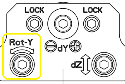
Rotation-Y In case the modulation values between the left and right image areas are significantly different, the camera can be rotated using Rot-Y.
Note: The change of the Rot-Y has a direct effect on delta X, here it must be checked whether the complete alignment adapter must be realigned for the X positioning. | |
Re-check the adjusted Parameters. Due to the dependencies of individual parameters, the previously set adjustment must a be checked iteratively and readjusted accordingly.
| |
.png)

.png)


.PNG)
.PNG)
.PNG)
.PNG)
.png)

