The parameters of this group describe how to influence and determine the image size and format. It also provides the necessary information to acquire and to display the image data. It assumes that the device has a source of data that generates a single rectangular image. This image can be entirely or partially streamed out of the device using one or many Region of interest (ROI).
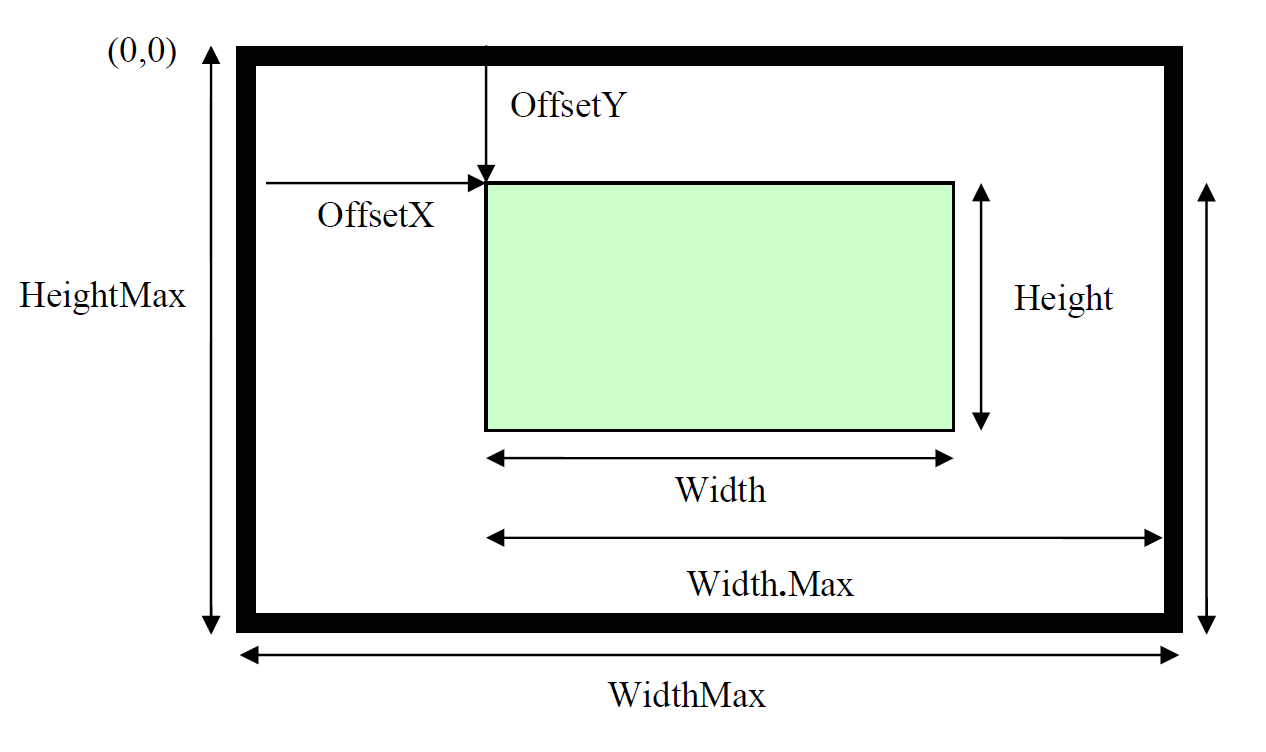
Image is taken from SFNC 2.4 p. 109
The sensor provides Sensor Width pixels.
The parameters ReverseX can be used to flip the image along the X-axis. The flipping is done before the Region of interest is applied.
Within the shrunk image the user can set a Region of interest using the parameters OffsetX, Width, and Height. The resulting image has Width time Height pixels. OffsetX refers to the upper left corner of the image which has the coordinate (0, 0).
The parameters Region Selector and Region Mode can be used to select and control each Region individually. All measures are given in pixel. As a result, the values should not change if the Pixel Format changes. For monochrome cameras, each pixel corresponds to a single gray value.
For color cameras in RGB mode each pixel corresponds to one RGB triplet.
The parameter Height describes the height of the image in lines.
Sensor Width
Name | SensorWidth | Standard |
|---|---|---|
Description | Effective width of the sensor in pixels. | |
Interface | Integer | |
Access mode | Read only | |
Adjustable while grabbing | - | |
Value range | Depends on the built-in sensor. | |
Default value | 1 | |
Availability | ALL | |
Notes | - | |
Error behavior | - | |
Sensor Height
Name | SensorHeight | Standard |
|---|---|---|
Description | Effective height of the sensor in pixels. | |
Interface | Integer | |
Access mode | Read only | |
Adjustable while grabbing | - | |
Value range | 1 | |
Default value | 1 | |
Availability | ALL | |
Notes | - | |
Error behavior | - | |
Sensor Color Filter
Name | SensorColorType | Custom |
|---|---|---|
Description | Specifies the sensor color filter. | |
Interface | Enumeration | |
Access mode | Read only | |
Adjustable while grabbing | - | |
Value range | See enum entry table below. | |
Default value | - | |
Availability | - | |
Notes | Only the display name is changed to sensor color filter for backward compatibility. | |
Error behavior | - | |
Sensor Color Filter Enum Entries:
Name | Description |
|---|---|
White | White |
RGBW | Red, Green, Blue and White |
RGBWIr | Red, Green, Blue, White and Infrared |
RGBIr | Red, Green, Blue and Infrared |
Width Max
Name | WidthMax | Standard |
|---|---|---|
Description | Maximum width of the image (in pixels). The dimension is calculated after horizontal binning, decimation or any other function changing the horizontal dimensions of the image. | |
Interface | Integer | |
Access mode | Read only | |
Adjustable while grabbing | - | |
Value range | >0 | |
Default value | SensorWidth | |
Availability | ALL | |
Notes | - | |
Error behavior | - | |
Height Max
Name | HeightMax | Standard |
|---|---|---|
Description | Maximum height of the image (in pixels). This dimension is calculated after vertical binning, decimation or any other function changing the vertical dimensions of the image. | |
Interface | Integer | |
Access mode | Read only | |
Adjustable while grabbing | - | |
Value range | >0 | |
Default value | - | |
Availability | ALL | |
Notes | The maximum height depends on your PC and Frame grabber configuration. | |
Error behavior | - | |
Region Selector
Name | RegionSelector | Standard |
|---|---|---|
Description | Selects the Region of interest to control. | |
Interface | Enumeration | |
Access mode | Read/Write | |
Adjustable while grabbing | - | |
Value range | See enum entry table below. | |
Default value | - | |
Availability | ALL | |
Notes | - | |
Error behavior | - | |
Region Selector Enum Entries:
Name | Description |
|---|---|
Region1 | Selected feature will control the region 1 |
Region2 | Selected feature will control the region 2. For ax_dsxge only. |
Region Mode
Name | RegionMode[RegionSelector] | Standard |
|---|---|---|
Description | Controls whether the selected Region of interest is active and streaming. | |
Interface | Enumeration | |
Access mode | Read/Write | |
Adjustable while grabbing | No | |
Value range | See enum entry table below. | |
Default value | - | |
Availability | ALL | |
Notes | - | |
Error behavior | See the device error code documentation. | |
Region Mode Enum Entries:
Name | Description |
|---|---|
Off | Disable usage of the Region. For ax_dsxge only |
On | Enable usage of the Region. |
Width
Name | Width[RegionSelector] | Standard |
|---|---|---|
Description | Width of the Image provided by the device (in pixels). | |
Interface | Integer | |
Access mode | Read/Write | |
Adjustable while grabbing | No | |
Value range | [128 , Width Max] | |
Default value | WidthMax | |
Availability | ALL | |
Notes | The width value must be a multiple of eight for RGB. | |
Error behavior | See the device error code documentation. | |
Height
Name | Height[RegionSelector] | Standard |
|---|---|---|
Description | Height of the Image provided by the device (in pixels). | |
Interface | Integer | |
Access mode | Read/Write | |
Adjustable while grabbing | No | |
Value range | [16 , Height Max] | |
Default value | 1024 | |
Availability | ALL | |
Notes | This parameter influences the value range of AcquisitionFrameRate. Please read the AcquisitionFrameRate feature documentation for further details. | |
Error behavior | See the device error code documentation. | |
Offset X
Name | OffsetX[RegionSelector] | Standard |
|---|---|---|
Description | Horizontal offset from the origin to the region of interest (in pixels). | |
Interface | Integer | |
Access mode | Read/Write | |
Adjustable while grabbing | No | |
Value range | ≥0 | |
Default value | 0 | |
Availability | ALL | |
Notes | - | |
Error behavior | See the device error code documentation. | |
Sensor Region Offset X
Name | SensorRegionOffsetX[RegionSelector] | Custom |
|---|---|---|
Description | Horizontal offset from the origin to the region of interest in sensor coordinates (pixels). | |
Interface | Integer | |
Access mode | Read only | |
Adjustable while grabbing | No | |
Value range | ≥0 | |
Default value | 0 | |
Availability | ALL | |
Notes | The display name is just Sensor Offset X. | |
Error behavior | See the device error code documentation. | |
Sensor Region Width
Name | SensorRegionWidth[RegionSelector] | Custom |
|---|---|---|
Description | Width of the selected region of interest in sensor coordinates (in pixels). | |
Interface | Integer | |
Access mode | Read only | |
Adjustable while grabbing | No | |
Value range | ≥0 | |
Default value | 0 | |
Availability | ALL | |
Notes | The display name is just Sensor Width. The feature resides below the Region Selector. There is a SensorWidth feature defining the sensor’s full width which resides in the top level of the image format control category. | |
Error behavior | See the device error code documentation. | |
Binning Horizontal
Name | BinningHorizontal | Standard | |
|---|---|---|---|
Description | Number of horizontal photo-sensitive cells to combine. This increases the intensity (or signal-to-noise ratio) of the pixels and reduces the horizontal resolution (width) of the image. | ||
Interface | Integer | ||
Access mode | Read/Write | ||
Adjustable while grabbing | No | ||
Value range | Variant | Value Range | |
ax_X | 1,2,4,8,16 | ||
g8_X | 1,2,4,8,16 | ||
Default value | 1 – Indicates that no horizontal binning is performed by the camera. | ||
Availability | ALL | ||
Notes | If you change this parameter, the Region OffsetX and Width is scaled according to the binning value. When Width is changed, the maximum BinningHorizontal value may be reduced and limited to that value. This is done to ensure that Width value doesn’t go below the minimum width value. | ||
Error behavior | See the device error code documentation. | ||
Decimation Horizontal Float
Name | DecimationHorizontalFloat | Custom |
|---|---|---|
Description | This is the same feature as DecimationHorizontal as defined in the SFNC. However, it supports float values for decimation. Horizontal sub-sampling of the image. This reduces the horizontal resolution (width) of the image by the specified horizontal decimation factor. | |
Interface | Float | |
Access mode | Read/Write | |
Adjustable while grabbing | Yes | |
Value range | [0.5 , 3.999] | |
Default value | 1.0 | |
Availability | ALL | |
Notes | A value of 1 indicates that the camera performs no horizontal decimation. If you change this parameter, the Region OffsetX and Width are scaled according to the decimation value. Please check these parameters after adapting Decimation Horizontal. When Width is changed, the maximum DecimationHorizontalFloat value may be reduced and limited to that value. This is done to ensure that Width value doesn’t go below the minimum width value. | |
Error behavior | See the device error code documentation. | |
Reverse X
Name | ReverseX | Standard |
|---|---|---|
Description | Flip the image sent by the device horizontally. | |
Interface | Boolean | |
Access mode | Read/Write | |
Adjustable while grabbing | No | |
Value range | True – Horizontally flipped image False – Normal Image | |
Default value | False | |
Availability | ALL | |
Notes | This feature is effective only if Test Pattern is set to Off. | |
Error behavior | - | |
Pixel Format
Name | PixelFormat | Standard | |
|---|---|---|---|
Description | Format of the pixels provided by the device. It represents all the information provided by PixelSize, PixelColorFilter combined in a single feature. | ||
Interface | Enumeration | ||
Access mode | Read/Write | ||
Adjustable while grabbing | No | ||
Value range | See enum entry table below. | ||
Default value | Variant | Value | |
Color Camera | RGB8 | ||
Mono Camera | Mono8 | ||
Availability | ALL | ||
Notes | - | ||
Error behavior | See the device error code documentation. | ||
Pixel Format Enum Entries:
Name | Availability | Description |
|---|---|---|
Mono8 | ALL | |
Mono10 | ALL | |
Mono12 | ALL | |
RGB8 | ALL | |
RGB10 | ALL | |
RGB12 | ALL | |
RGB10p32 | - | 32-bits per pixel RGB format. The bit depth is 10-bits. Please check the PFNC (Pixel Format Naming Convention) for more details – Not available for g8_dxge packages! |
BGR8 | X_DXGE | 24 bits per pixel BGR linear memory |
RGBa8 | g8_X p6_nxge | 32 bits per pixel RGBa linear memory. Component ‘a’ contains Infrared (Ir) or White(W). |
RGBa10 | g8_X p6_nxge | RGBa at 10bit unpacked. Component ‘a’ contains Infrared (Ir) or White(W). |
RGBa12 | g8_X p6_nxge | RGBa at 12bit unpacked. Component ‘a’ contains Infrared (Ir) or White(W). |
Pixel Color Filter
Name | PixelColorFilter | Standard | |
|---|---|---|---|
Description | Selects the type of color filter that is applied to an image. | ||
Interface | Enumeration | ||
Access mode | Read/Write | ||
Adjustable while grabbing | No | ||
Value range | See enum entry table below. | ||
Default value | Variant | Value | |
ax_X | RGB | ||
g8_X | RGBIr | ||
p6_nxge | RGBIr | ||
p16_CXP | RGBIr | ||
ALL | |||
Availability | ALL | ||
Notes | For mono cameras the pixel color filter will be White only. | ||
Error behavior | See the device error code documentation. | ||
Pixel Color Filter Enum Entries:
Name | Availability | Description |
|---|---|---|
RGB | ALL | Three color planes RGB at the sensor is selected. |
RGBIr | p16_CXPp6_nxgeg8_X | Four color planes RGB and Infrared at the sensor is selected. Infrared is transmitted as component ‘a’ in the pixel format RGBa8, RGBa10 and RGBa12. |
RGBW | p16_CXPp6_nxge | Four color planes RGB and White at the sensor is selected. White is transmitted as component ‘a’ in the pixel format RGBa8, RGBa10 and RGBa12. |
White | g8_X | Only White plane at the sensor is selected |
Infoblock Mode
Name | InfoBlockMode | Standard |
|---|---|---|
Description | The info block can be enabled for the first line, for each line or for first and each line. | |
Interface | Enumeration | |
Access mode | Read/Write | |
Adjustable while grabbing | Yes | |
Value range | Enum entries table below. | |
Default value | Infoblock off | |
Availability | ALL | |
Notes | So far not all entries are working. There may be even differences between variants of allPIXAevo. | |
Error behavior | none | |
Info block Mode Entries:
Name | Description |
|---|---|
Off | No info block is displayed in the image. |
Firstline | First line Info block which is in line 0 of each transmitted image is displayed. |
Eachline | In each line from line 0 of each transmitted image the Each line info block is displayed. |
FirstandEachLine | First and each line info block are displayed in each image. In case both FirstlineandEach line info block are active, Eachline info block is always displayed from line 1 in every transmitted image! |
Pixel | 0 | 1 | 2 | 3 | 4 | 5 | 6 | 7 | 8 | 9 | 10 | 11 | 12 | 13 | 14 | 15 | 16 | 17 | 18 | 19 | 20 | 21 | 22 | 23 |
|---|---|---|---|---|---|---|---|---|---|---|---|---|---|---|---|---|---|---|---|---|---|---|---|---|
Line 0 | MARKER | SERIAL | MARKER | IMAGE | EXPOSURE TIME | MARKER | LINE TIME | ENCODER | ERROR | TIME STAMP | MARKER | |||||||||||||
Information | Channel Content1 | Description | |||||||||||||
|---|---|---|---|---|---|---|---|---|---|---|---|---|---|---|---|
MARKER | DIVERSE | Markers are used to mark the info block with red pixels.
| |||||||||||||
SERIAL NUMBER | SAME | These pixels encode the serial number of the camera.
| |||||||||||||
IMAGE COUNT | SAME | These pixels encode the image count of the camera.
| |||||||||||||
EXPOSURE TIME | SAME | This is the current Exposure Time in camera internal clock cycles.
To decode the exposure time, use the following formula:
| |||||||||||||
LINE TIME | SAME | This is the current line time in camera internal clock cycles.
Package 2.1.2 and later:
| |||||||||||||
ENCODER CLOCKS | SAME | This is a 32-bit counter starting at power on with 0.
When setting EncoderSourceA to Off the encoder clock counter will be reset. | |||||||||||||
ERROR CODE | UNUSED | CURRENTLY UNUSED PRESET WITH ZERO | |||||||||||||
TIMESTAMP | SAME | Timestamp starts counting from boot.
1MS= Milliseconds To achieve the milliseconds part of the timestamp the Content of Px21 must be multiplied by four. | |||||||||||||
1 SAME indicates that all color channels contain the same value. It is sufficient to evaluate a single color component. DIVERSE indicates different values for individual color channels which should be taken into account when composing the information.
Each Line info block format
Pixel | 0 | 1 | 2 | 3 | 4 | 5 | 6 | 7 | 8 | 9 |
RED | MARKER | ERROR CODE | SPEED2HIGH | ENCODER CLOCKS | NEXT LINE POSITION | TIME STAMP | UNSUPPORTED | UNSUPPORTED | LINE STATUS/SCAN-DIR | MARKER |
LINE TIME | ||||||||||
GREEN | CONTINUOUS LINE COUNT | LINE COUNT | ||||||||
BLUE |
Information | Channel Content1 | Description | ||||||||||||
|---|---|---|---|---|---|---|---|---|---|---|---|---|---|---|
CONTINUOUS LINE COUNT | DIVERSE | This is the continuous line count across image boundaries.
| ||||||||||||
ERROR CODE | DIVERSE | This is an error code. Currently not used!
| ||||||||||||
LINE COUNT | DIVERSE | This is a line counter starting from image start.
| ||||||||||||
SPEED2HIGH | DIVERSE | This bit is set if the line trigger exceeds the cameras maximum line rate. This is Bit7 of Px1Red.
| ||||||||||||
LINE TIME | DIVERSE | This is the current measured line time in camera internal clock cycles.
Package 2.1.2 and later:
| ||||||||||||||||||||
ENCODER CLOCKS | DIVERSE | This is a 24-bit counter starting at power on with 0.
When setting EncoderSourceA to Off the encoder clock counter will be reset. | ||||||||||||||||||||
NEXT LINE TRIGGER POSITION | DIVERSE | Information of the next line trigger position in encoder pulses (only at encoder mode). The calculated position is shown in a 16.8b value. If encoder averaging is used, the value is divided by the average size. At a slave camera, this field has the value zero.
To achieve the actual value, follow this formula: | ||||||||||||||||||||
TIMESTAMP | SAME | Timestamp starts counting from boot.
1MS= Milliseconds To achieve the milliseconds part of the timestamp the Content of Px5Blue must be multiplied by four. | ||||||||||||||||||||
LINE STATUS | DIVERSE | This entry reflects the logical level of the input lines before LineInverter. If LineInverter is enabled the value reflected by the Line Status feature is inverse.
| ||||||||||||||||||||
SCAN-DIR | DIVERSE | The scan direction
| ||||||||||||||||||||
1 SAME indicates that all color channels contain the same value. It is sufficient to evaluate a single color component. DIVERSE indicates different values for individual color channels which should be taken into account when composing the information.
Test Pattern Generator Selector
Name | TestPatternGeneratorSelector | Standard |
|---|---|---|
Description | Selects which test pattern generator is controlled by the TestPattern feature. | |
Interface | Enumeration | |
Access mode | Read/Write | |
Adjustable while grabbing | Yes | |
Value range | See enum entry table below. | |
Default value | ImageProcessing | |
Availability | ALL | |
Notes | - | |
Error behavior | - | |
Test Pattern Generator Selector Enum Entries:
Name | Description |
|---|---|
ImageProcessing | TestPattern feature controls the Image Processing test pattern generator. |
Test Pattern
Name | TestPattern[TestPatternGeneratorSelector] | Standard |
|---|---|---|
Description | Selects the type of test pattern that is generated by the device as image source. | |
Interface | Enumeration | |
Access mode | Read/Write | |
Adjustable while grabbing | No | |
Value range | See enum entry table below. | |
Default value | Off | |
Availability | ALL | |
Notes | - | |
Error behavior | See the device error code documentation. | |
Test Pattern Generator Selector Enum Entries:
Name | Description |
|---|---|
Off | Image is coming from the sensor. |
GreyHorizontalRamp | Image is filled horizontally with pixels that go from the darkest possible value to the brightest. |
GreyVerticalRamp | Image is filled vertically with pixels that go from the darkest possible value to the brightest. |
GreyHorizontalRampMoving | Image is filled horizontally with pixels that go from the darkest possible value to the brightest and that move horizontally from left to right at each frame. |
GreyVerticalRampMoving | Image is filled vertically with lines that go from the darkest possible value to the brightest and that move vertically from top to bottom at each frame. |
ColorRamps | Horizontal ramp in red color channel. Vertical and horizontal ramp in green color channel. Vertical ramp in blue color channel. |
TogglingPixels | Vertically and horizontally neighbored pixels have the inverse intensity value from each other. |
PinStripes | Fixed pin stripe pattern with configurable background. The background is configurable with the test pattern value feature. |
Test Pattern Value
Name | TestPatternValue[TestPatternGeneratorSelector] | Custom |
|---|---|---|
Description | Test-Pattern-specific value that influences the appearance of the generated image. | |
Interface | Integer | |
Access mode | Read/Write | |
Adjustable while grabbing | Yes | |
Value range | [0 – 4095] | |
Default value | 64 | |
Availability | ALL | |
Notes | - | |
Error behavior | See the device error code documentation. | |