The camera can be used to trigger up to four different flash controller channels synchronized to their line acquisition. You can acquire several images with different illumination colors simultaneously in a single scan using line-multiplexing. The camera starts a complete LED pattern sequence after each line trigger or after a sequence time in free-running mode.
The multi flash setup
The setup contains two Corona II illuminations which are controlled by the camera.
 | |||
| 1 | Line scan camera: scans the image line by line and communicates with the PC. | 2 | PC: performs subsequent processing of the image data and can control the illumination system. |
| 3 | Illumination: lights up the scan area. | 4 | Illumination controller: controls and monitors the illumination unit. |
| 5 | Speed detection: the encoder detects the speed of the conveyor belt and communicates with the camera. | ||
Connect the camera with the XLC4 controller
Any flash controller compatible to the electrical and timing specifications of the camera output interface can be synchronized. For best compatibility use the Chromasens illumination controller XLC4 (CP000411) illuminations from the Corona II product line.
Refer to the XLC4 controller manual.
Set up the flash controller
The camera provides up to four different outputs which can be operated individually to control flash controllers. Several flash outputs can be individually configured.
Flash controller: basic mode
The basic mode is a sequential flash with up to four channels.
|  |
Alternatively you can set up the basic flash controller in the camera feature tree by executing the following steps:
| Step | Feature name | Value |
|---|---|---|
| 1 | Led Flash Control Led Flash Enable | On |
| 2 | Led Flash Number of Pattern | <number of Pattern> |
| 3 | Led Flash Pattern Selector | Led Flash Pattern <1> |
| 4 | Out1 on Time | <on time in µs> |
| 5 | Pattern of Delay | <delay time in µs> |
| 6 | Led Flash Pattern Selector | Led Flash Pattern <n> |
| 7 | Out-n on Time | <on time in µs> |
| 8 | Pattern of Delay | <delay time in µs> |
| 9 | Flash frame control | – |
| 10 | Led Flash sequence time | – |
Flash controller: advanced mode
The advanced mode is a sequential flash with up to four channels and four patterns for each channel. The patterns are executed in a sequence. The sequence is repeated as long as scanning or triggering is active.
In this example two flash patterns are selected. The duration for each line pattern is set individually. All output channels are used. | 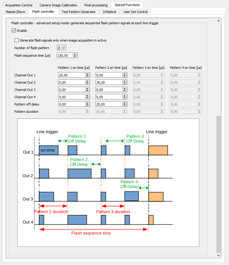 |
Alternatively you can set up the advanced flash controller in the camera feature tree by executing the following steps:
| Step | Feature name | Value |
|---|---|---|
| 1 | Led Flash Control Led Flash Enable | On |
| 2 | Led Flash Number of Pattern | <number of Pattern> |
| 3 | Led Flash Pattern Selector | Led Flash Pattern <1> |
| 4 | Out1 – 4 on Time | <on time in µs> |
| 5 | Pattern of Delay | <delay time in µs> |
| 6 | Led Flash Pattern Selector | Led Flash Pattern <n> |
| 7 | Out1 – 4 on Time | <on time in µs> |
| 8 | Pattern of Delay | <delay time in µs> |
| 9 | Flash frame control | – |
| 10 | Led Flash sequence time | – |
Deinterlace the image
The following image shows how to separate the flash channels on an example of two flash channels.
